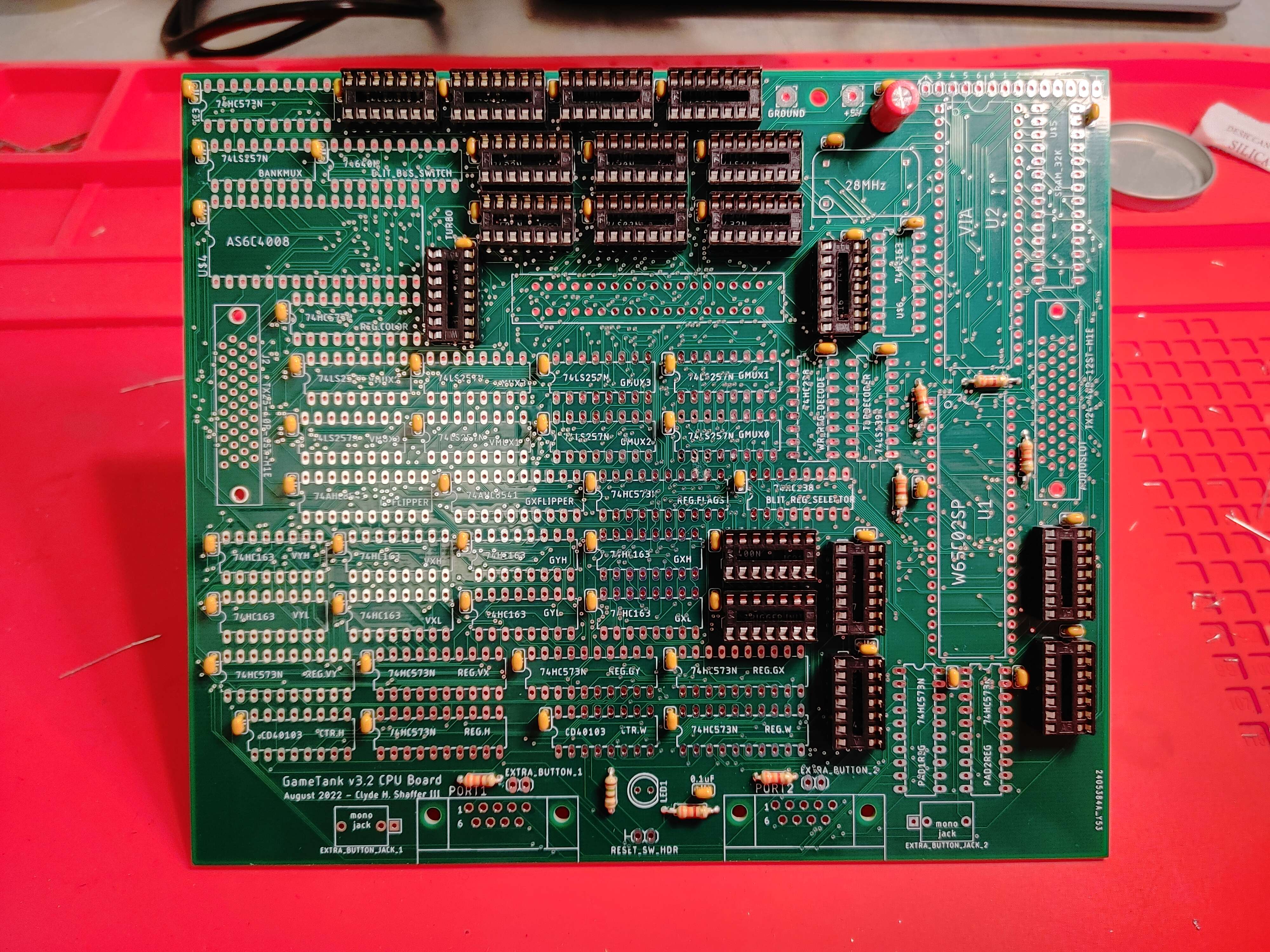
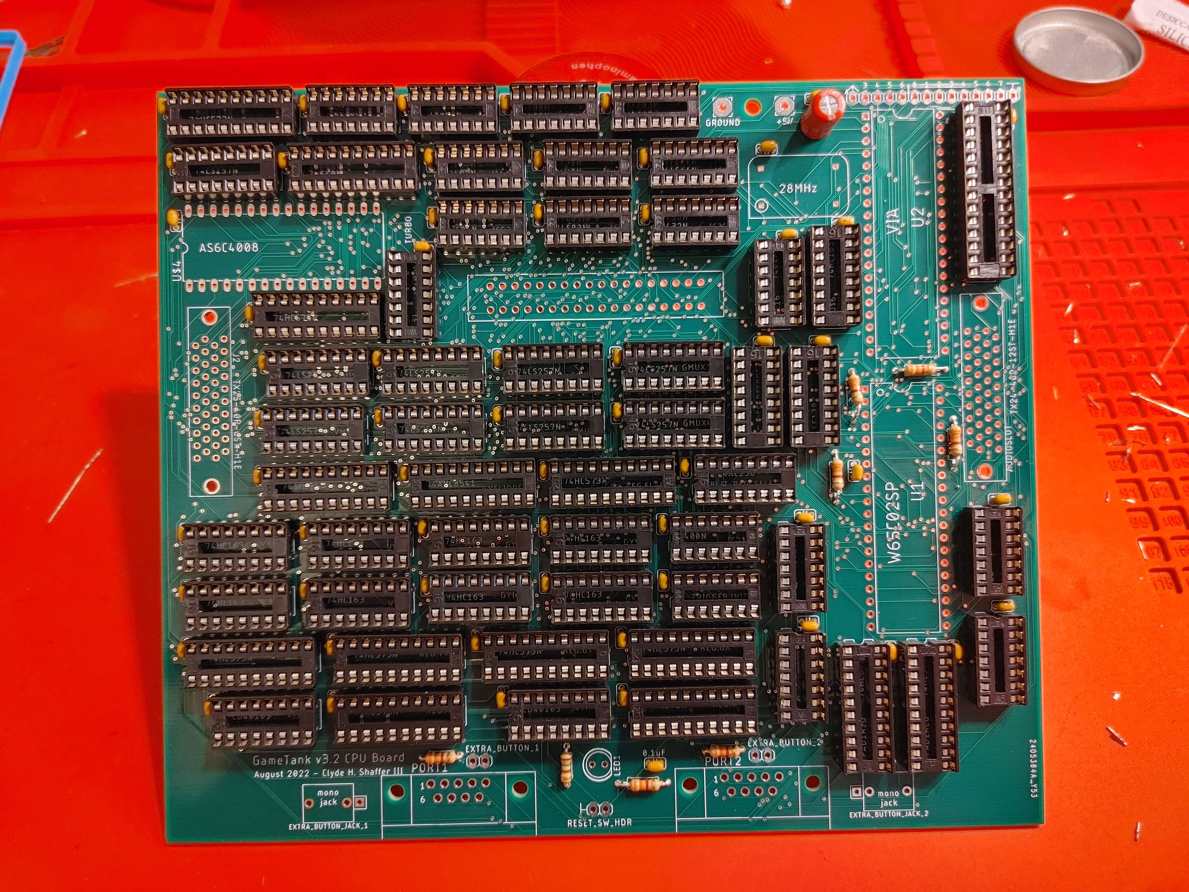
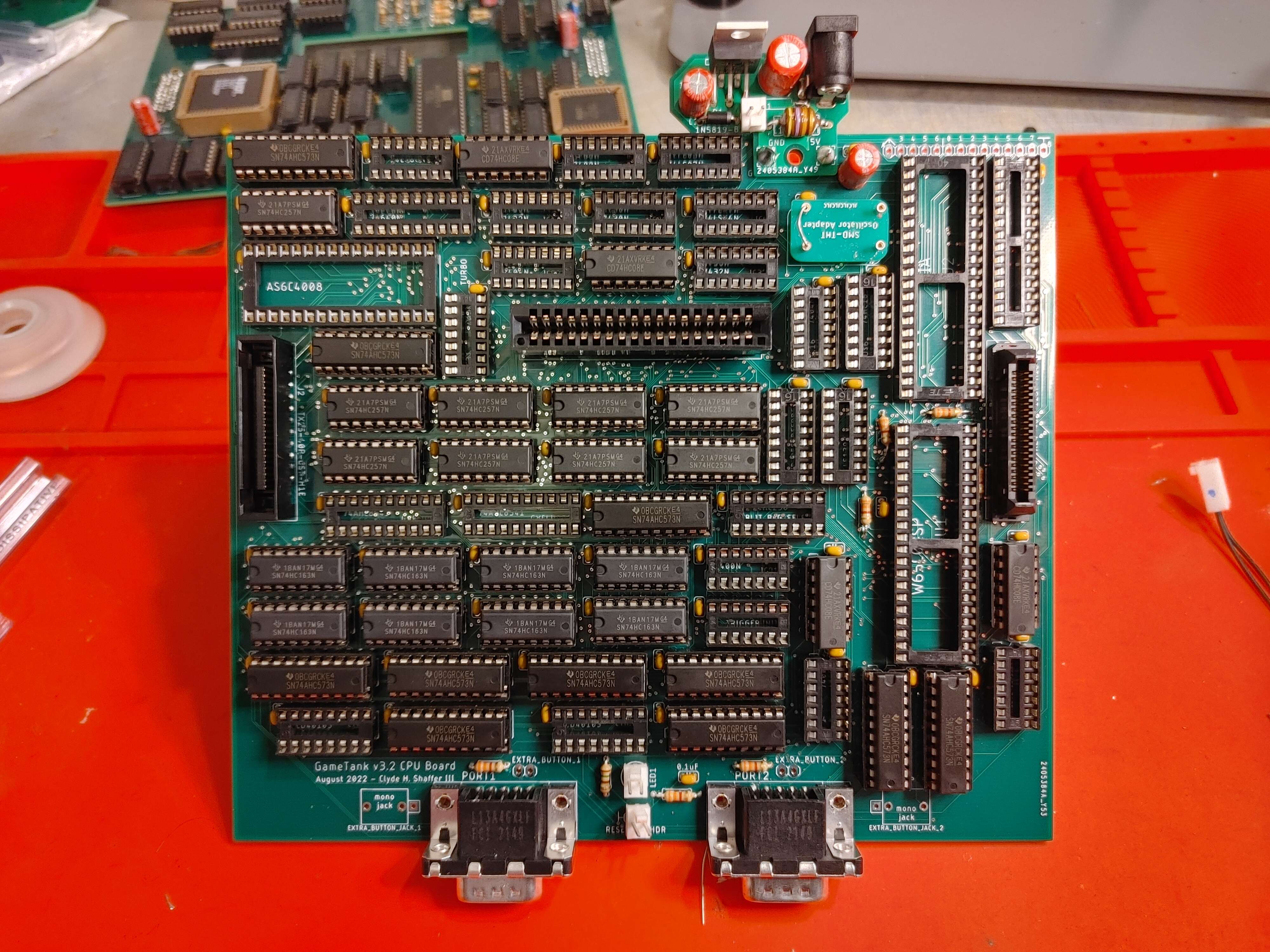
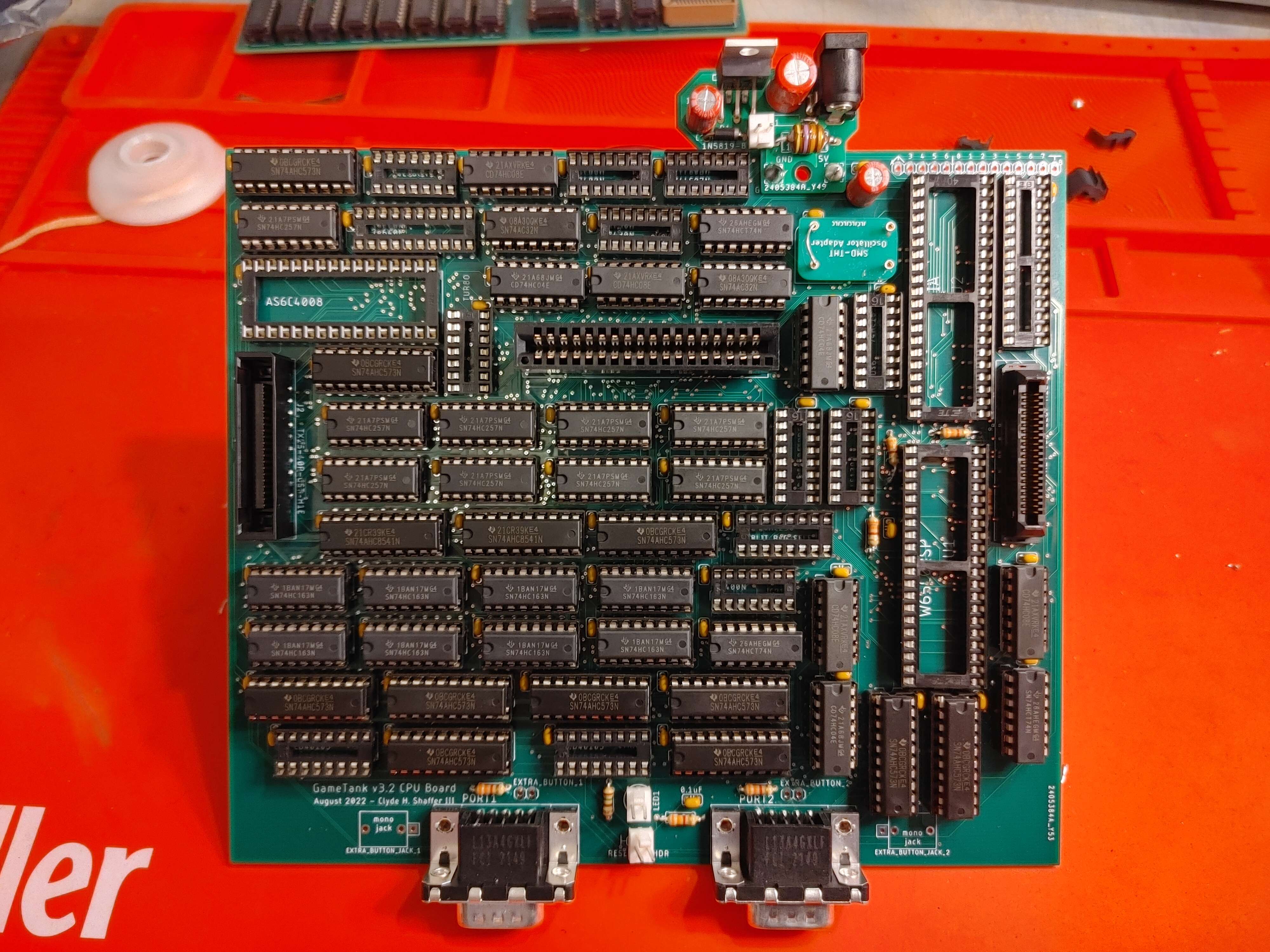
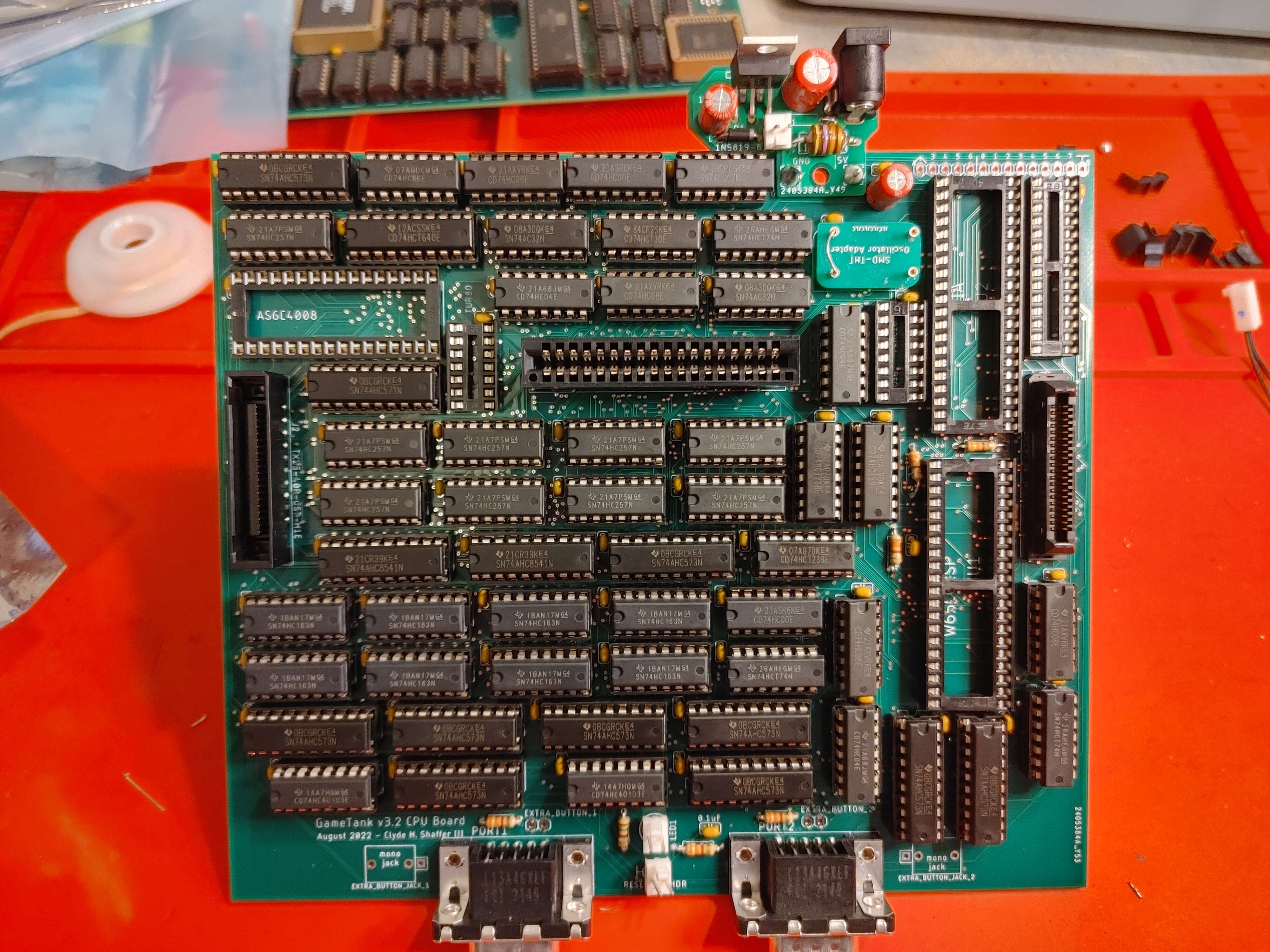
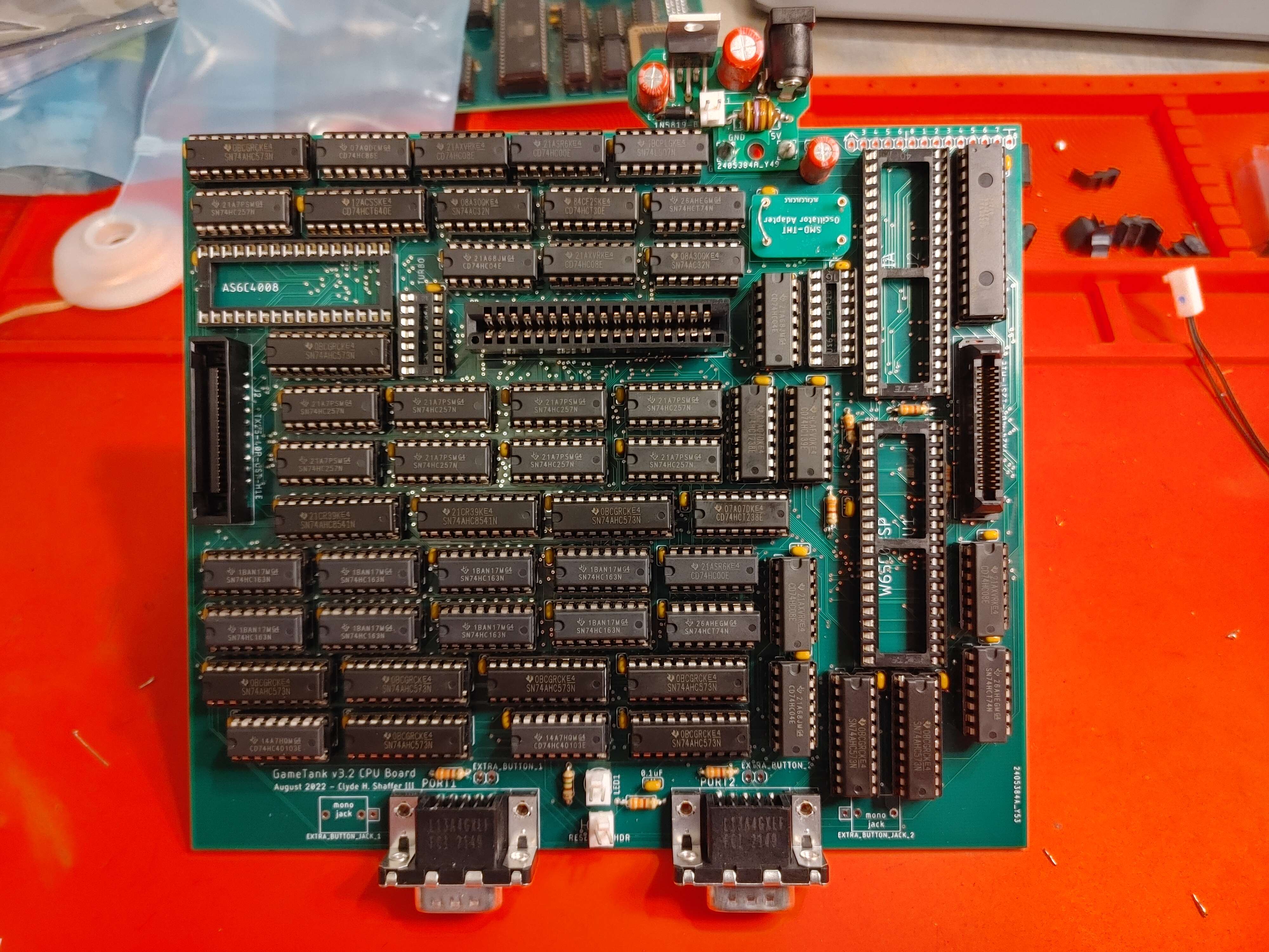
The CPU Board
Photos by @dwbrite
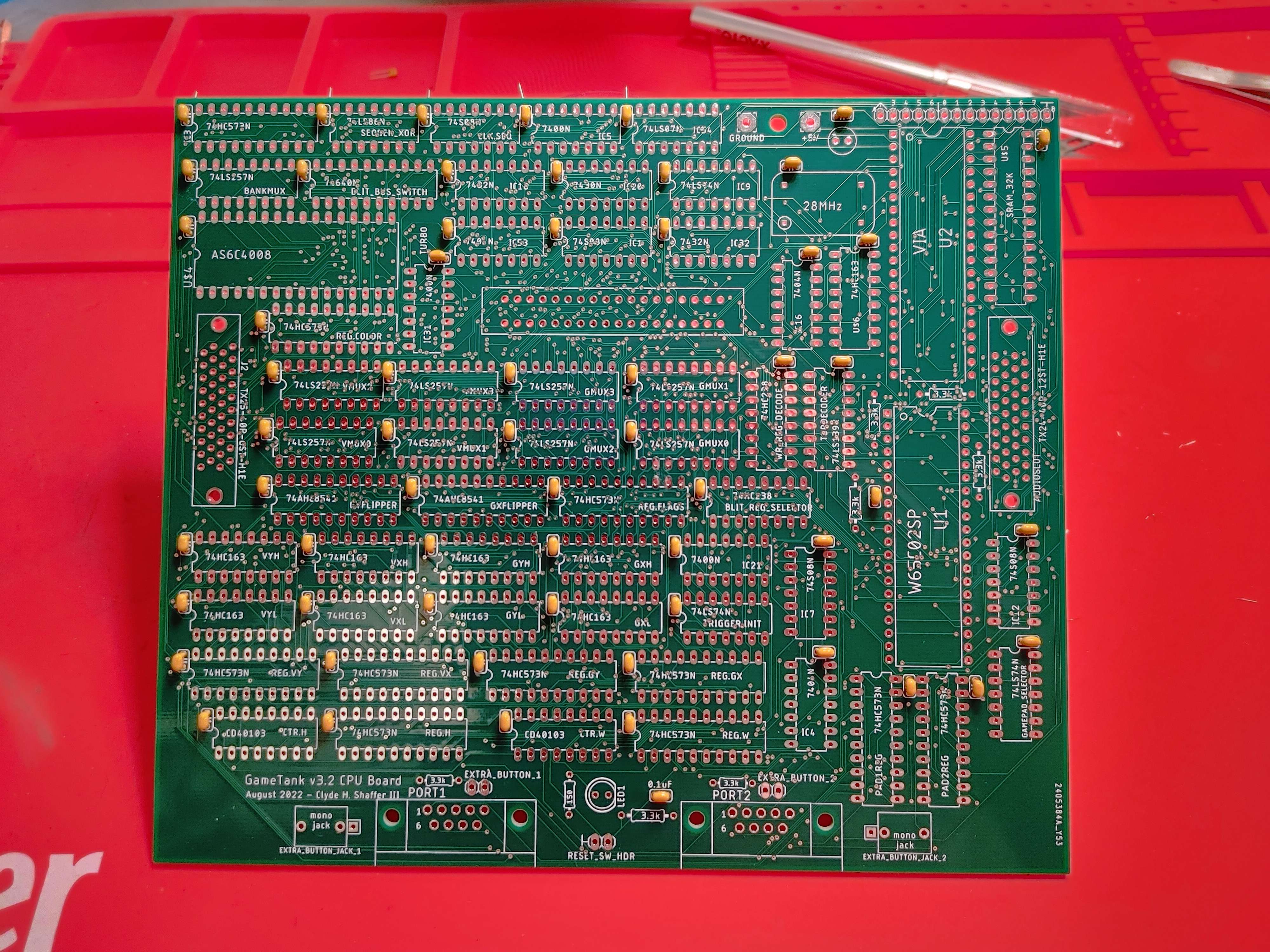
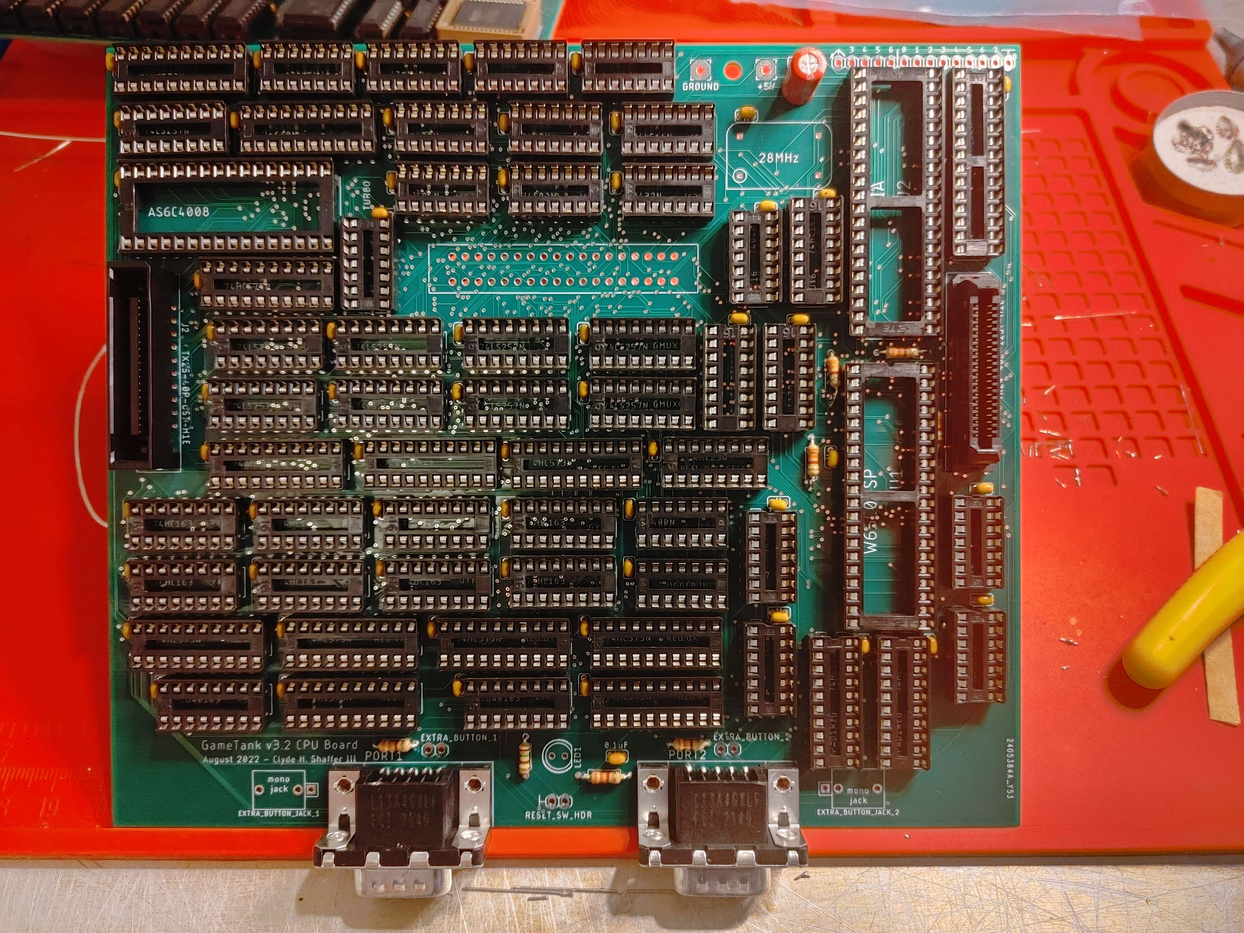
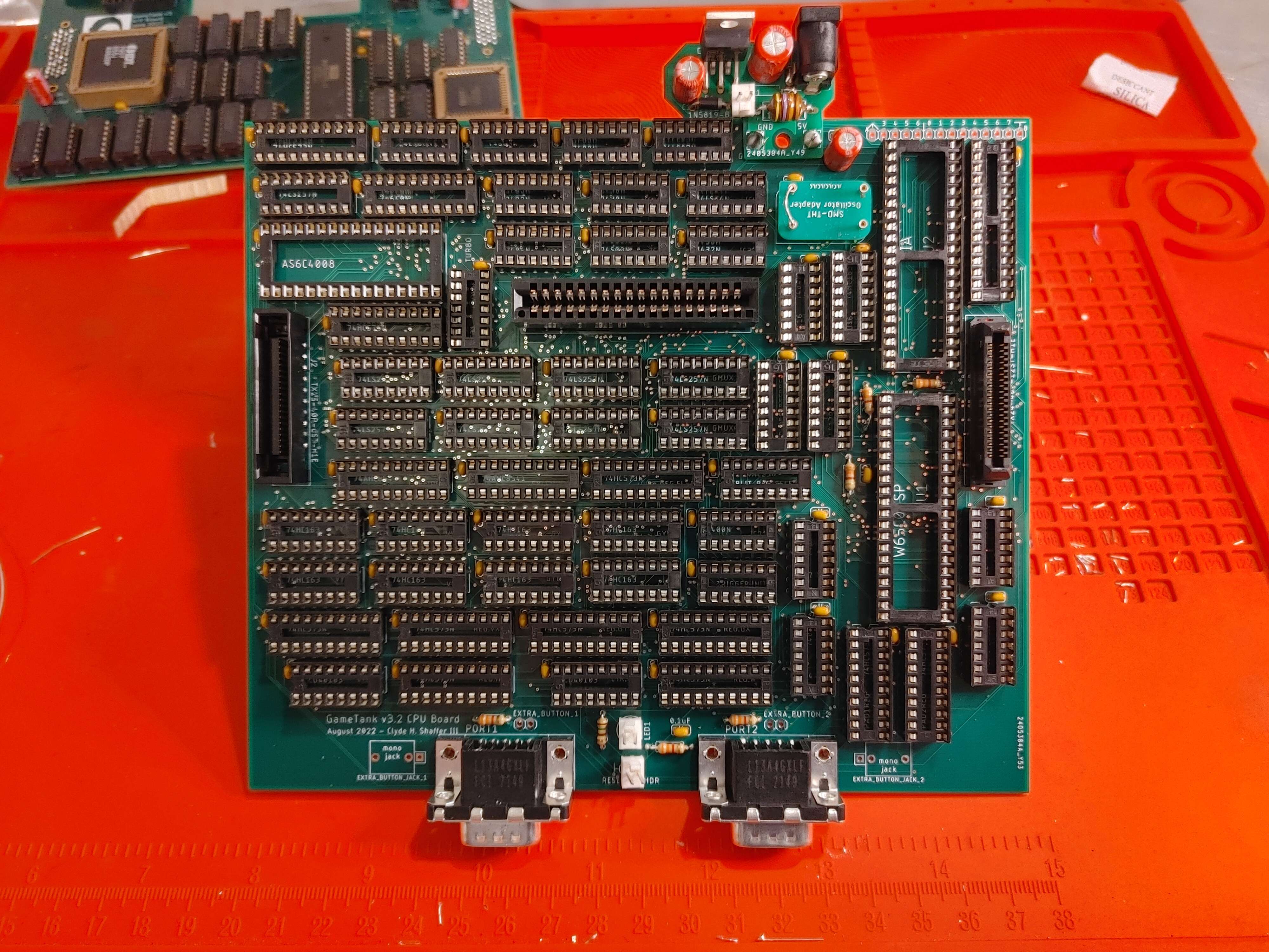
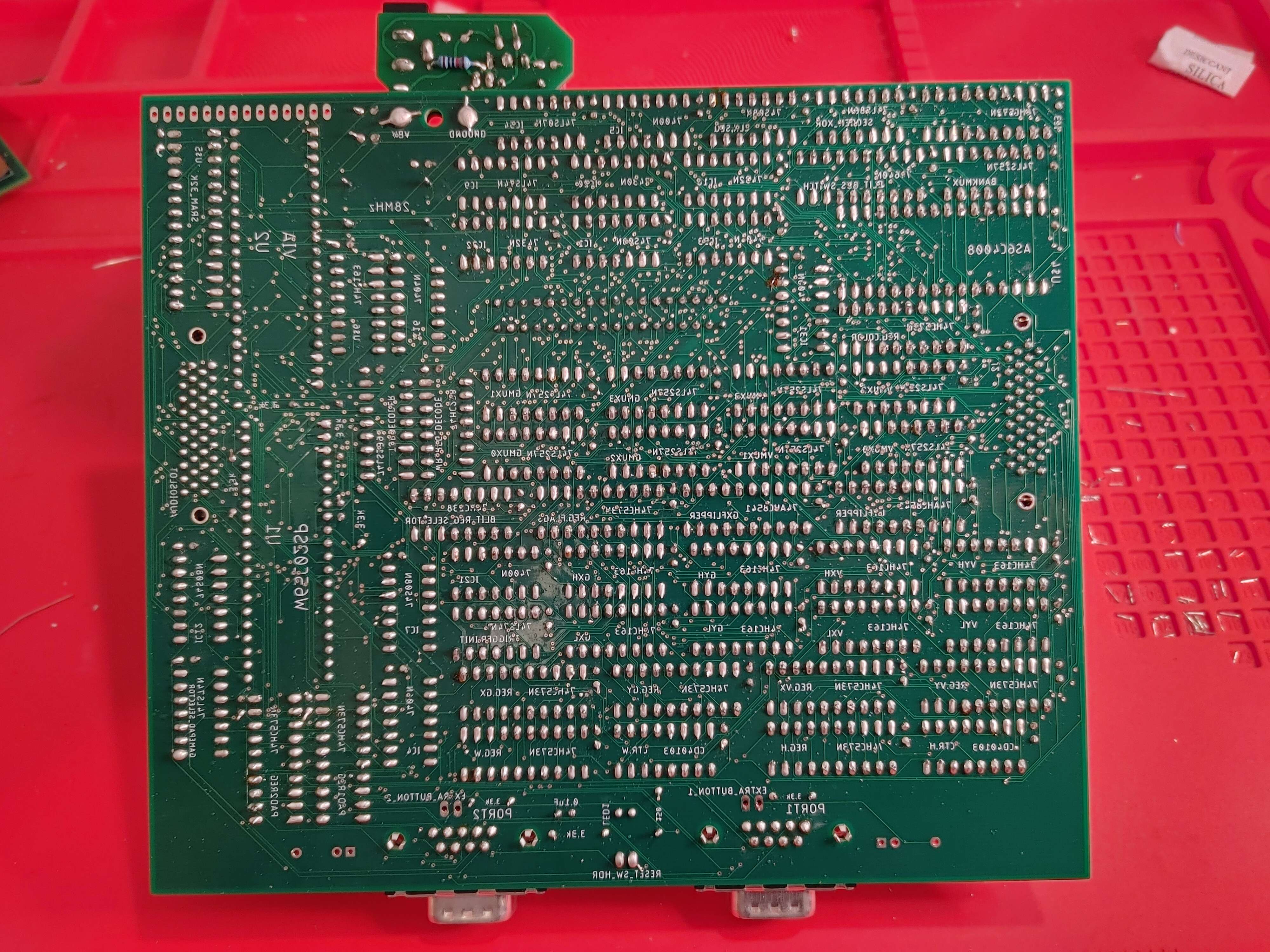
Step 1: Before we begin
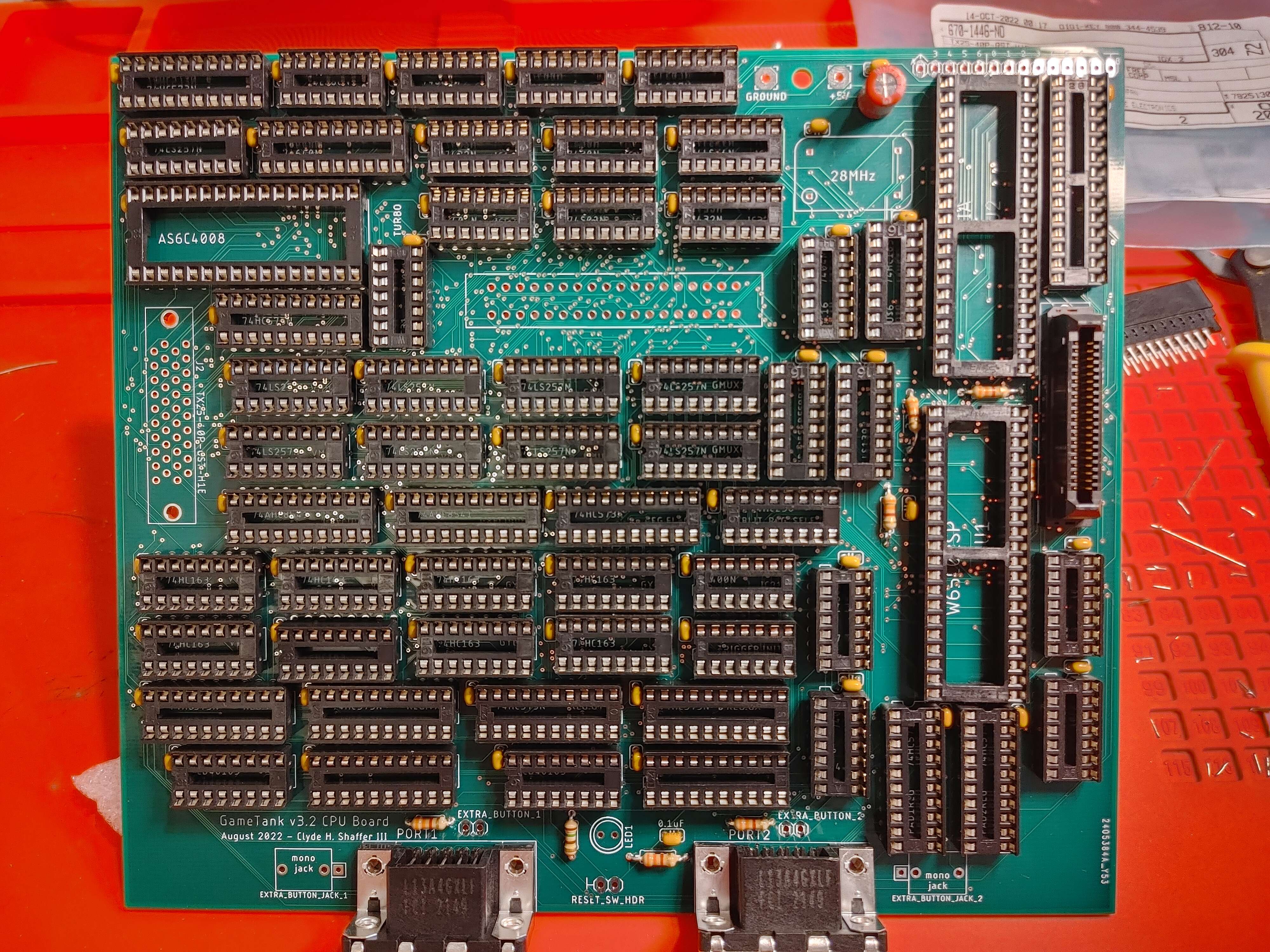
- This page will walk you through building the CPU Board, which holds the main system bus, blitter, cartridge ports, gamepad ports, and GPIO ports.
- The power board is also attached to the CPU board.
- In general we'll be placing the shorter components first.
- It will help to have a flat board handy, about the same size as the PCB. This can be used to keep parts from falling out as you flip the whole board to solder components.
Step 2: Bypass Capacitors
- The bypass capacitors smooth out the power supply to each chip.
- Every IC gets a 0.1uF capacitor next to it.
- There should be 63 of these
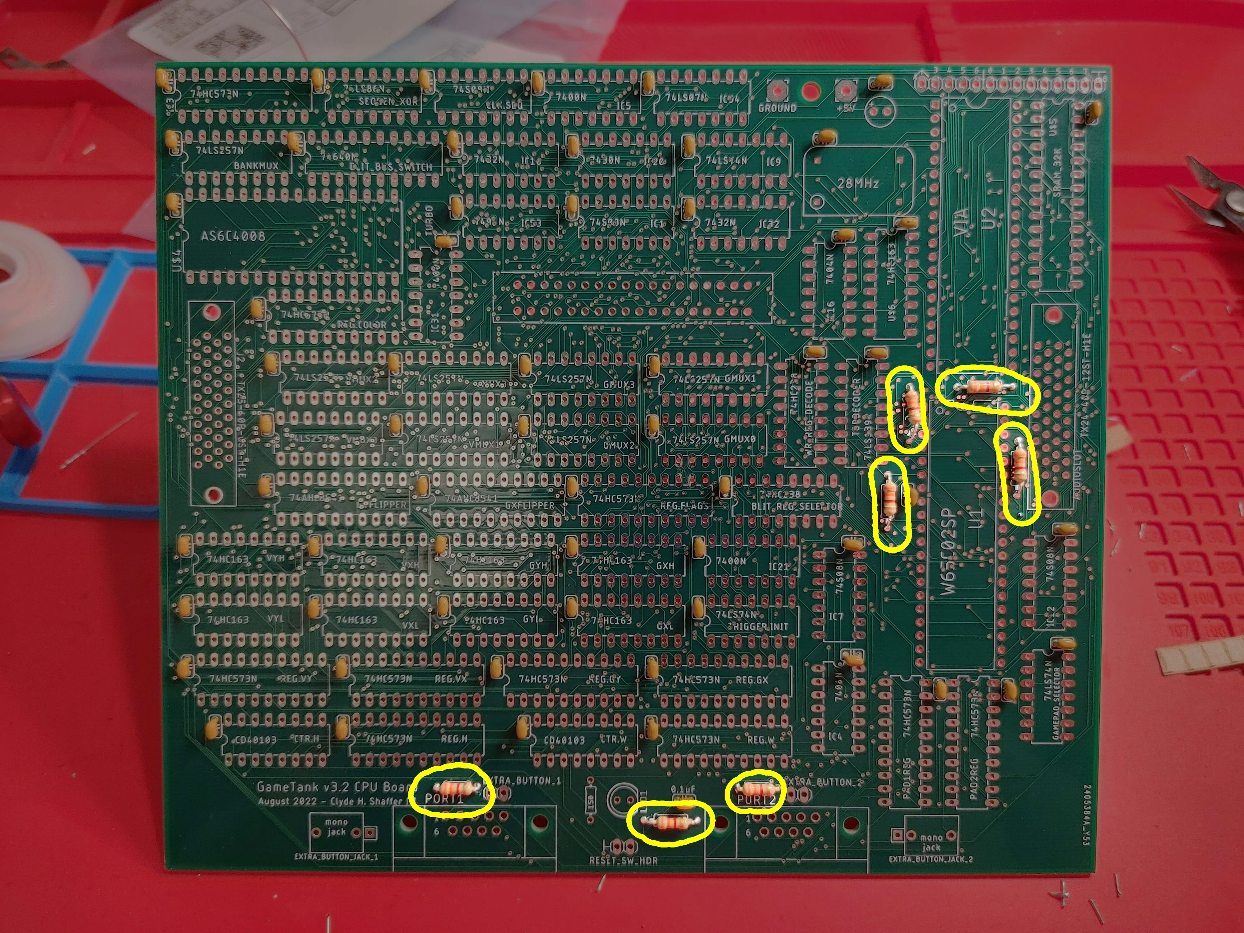
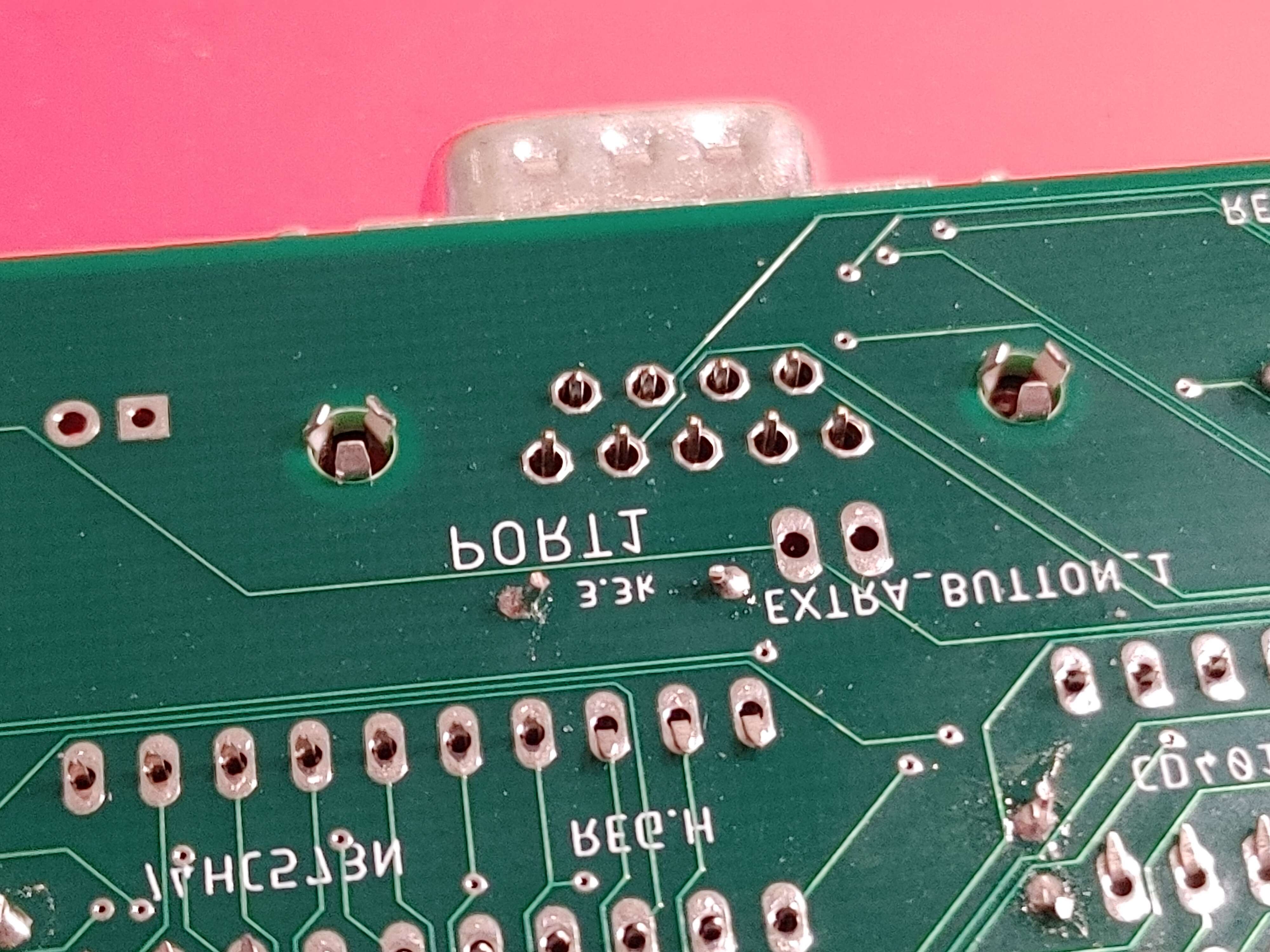
Step 3: Resistors
- 7 x 3.3k resistors (Orange Orange Red)
- 150 Ohm resistor next to LED1
- Polarity doesn't matter but they should be nice and close to the board to leave room for nearby components.
- After soldering and trimming resistors, set a couple of the trimmed leads aside to help with a later step.
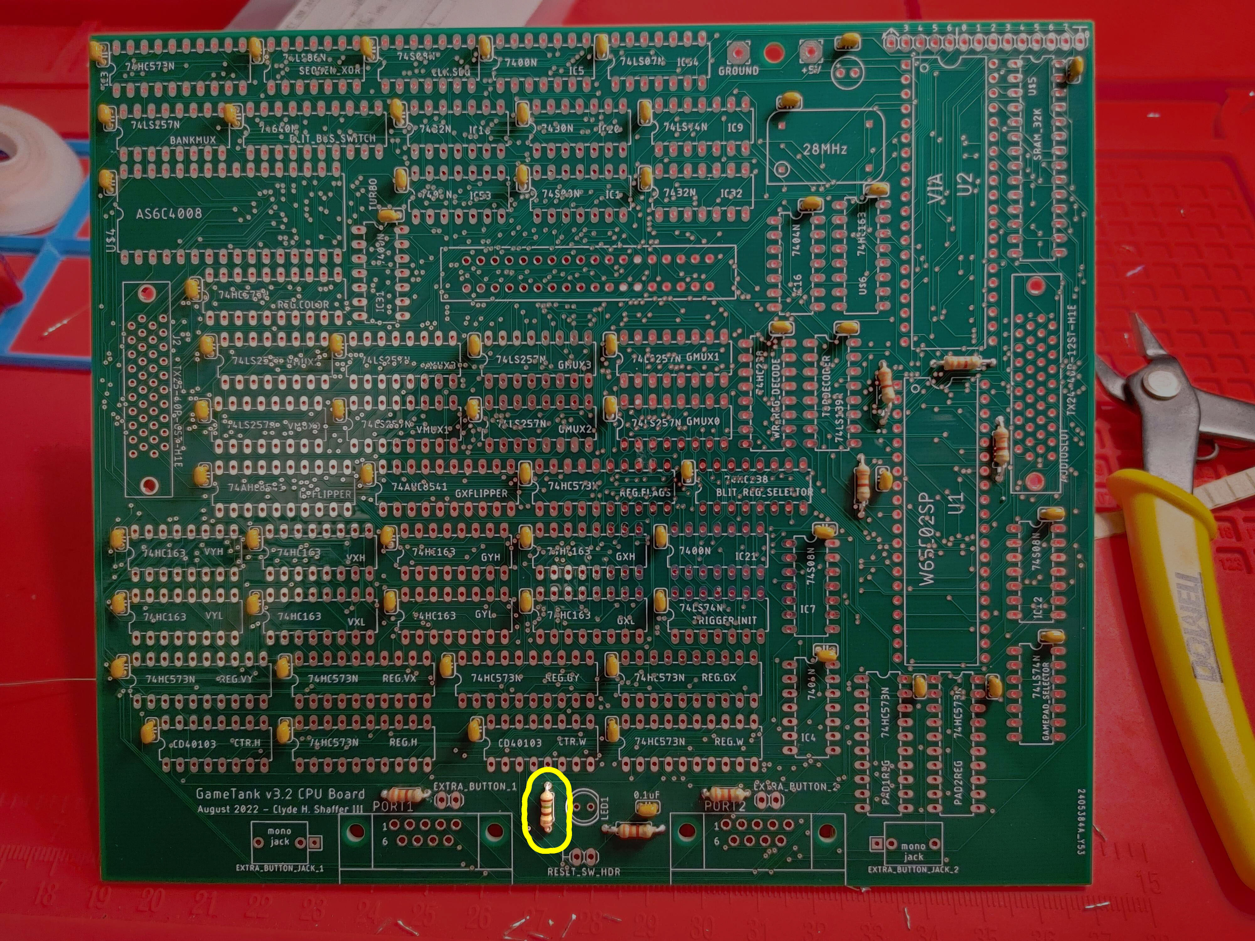
Step 4: Big Capacitors
- 220 Ohm capacitor near the power entry pads
- Be sure to align the stripe indicating the cathode (negative side) with the pad that does NOT have a "plus" + symbol
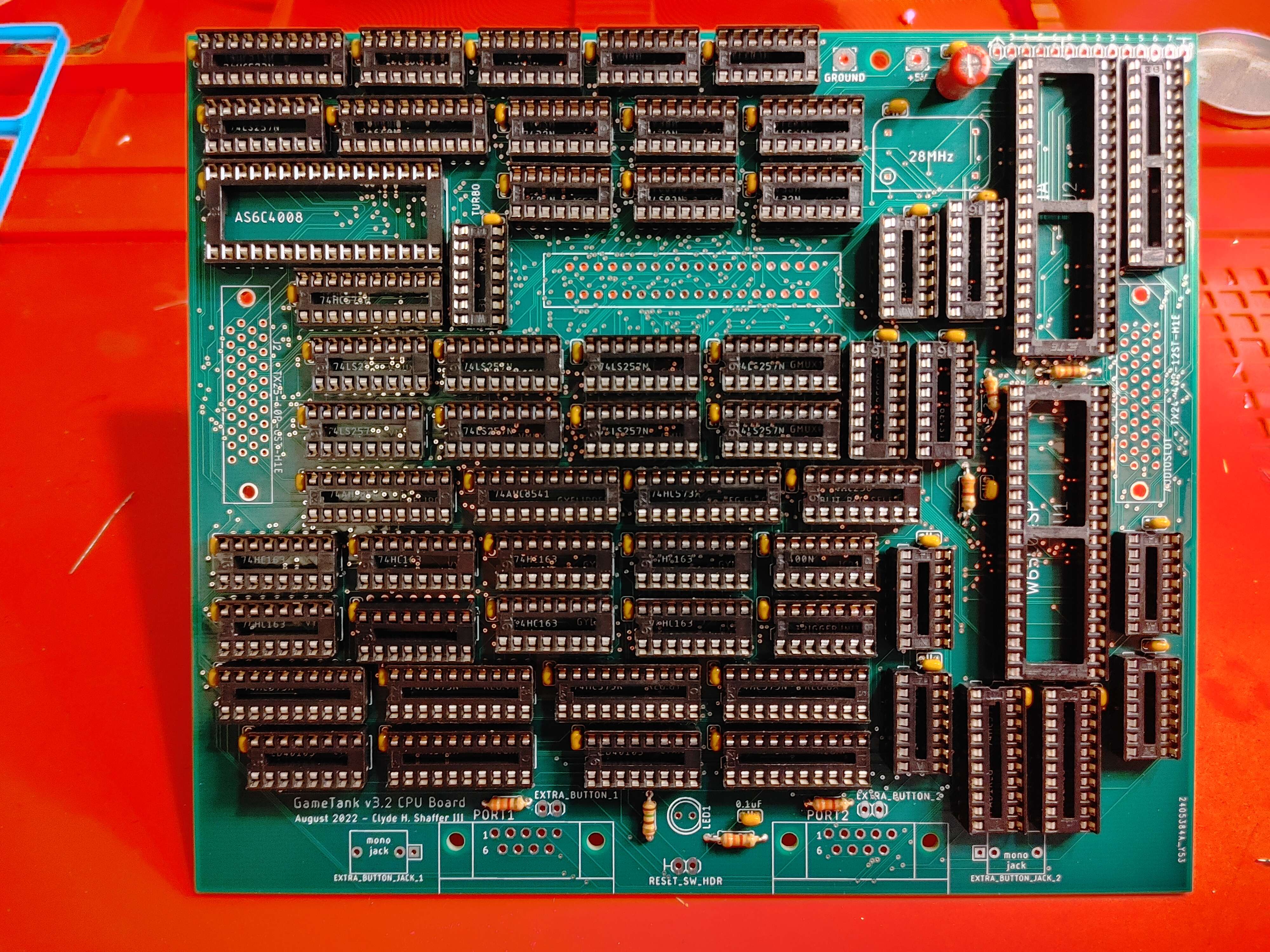
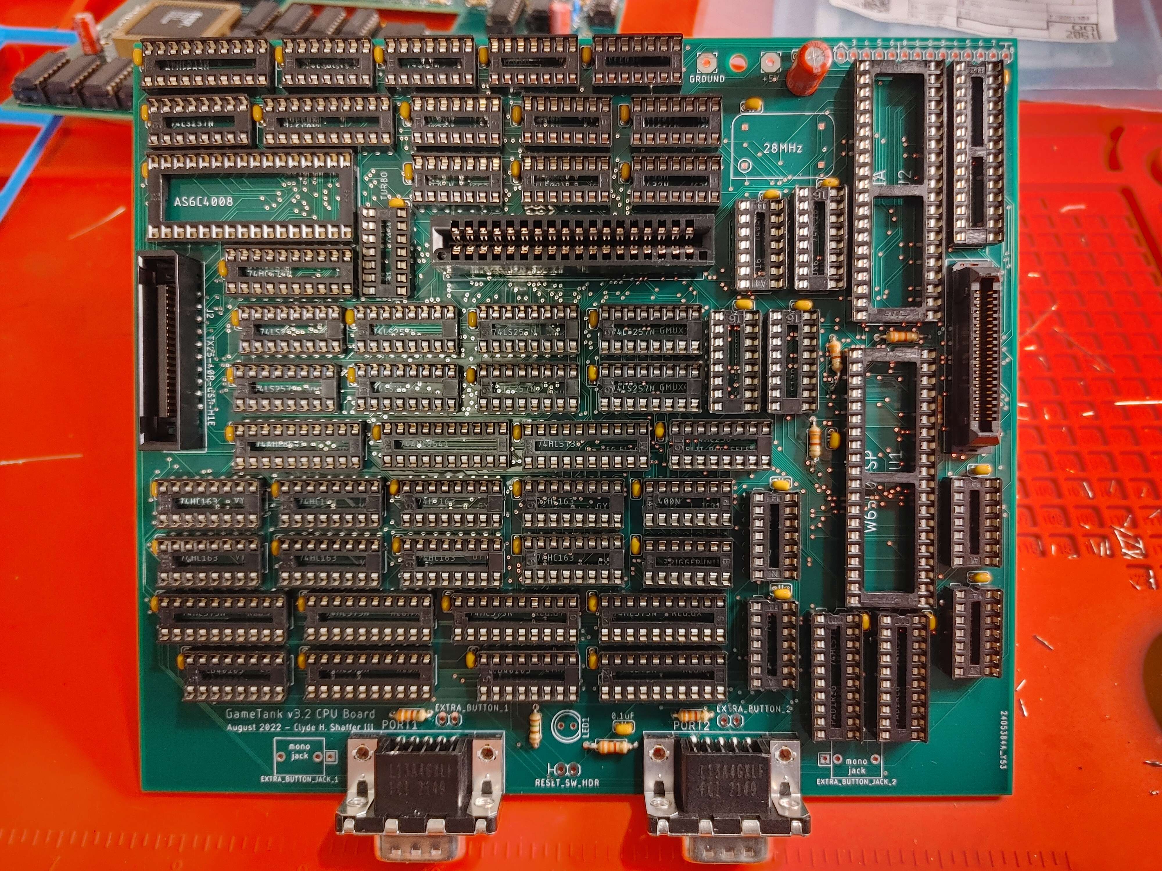
Step 5: DIP Sockets (Prelude)
- The next several steps will insert sockets for chips.
- The "wood board" method will still help if the sockets are still the tallest thing on the board.
- Otherwise, you can bend the socket pins outward to help them stay in the holes before soldering.
- BE SURE TO match the divot on the socket to the divot on the printed socket outline!
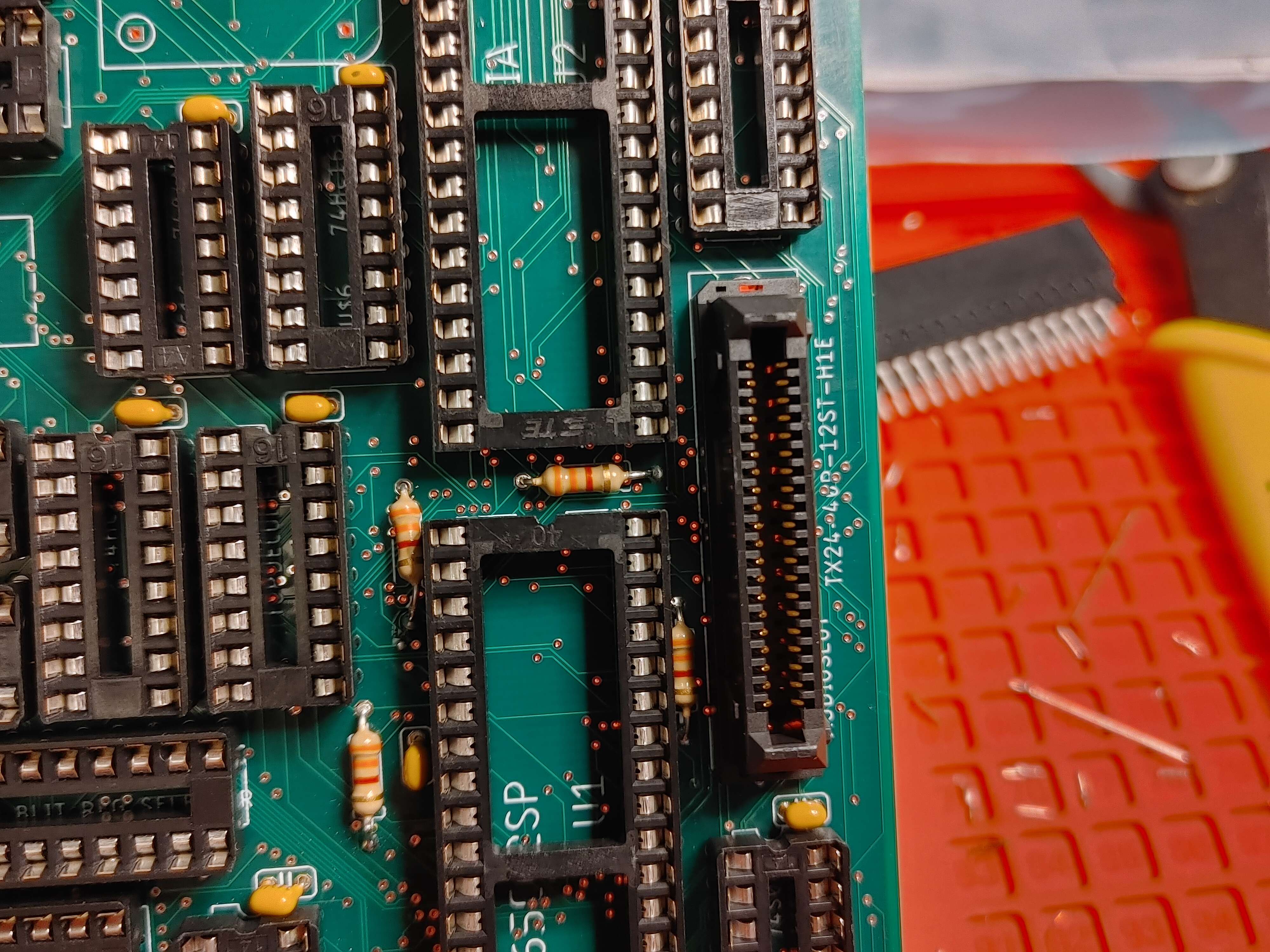
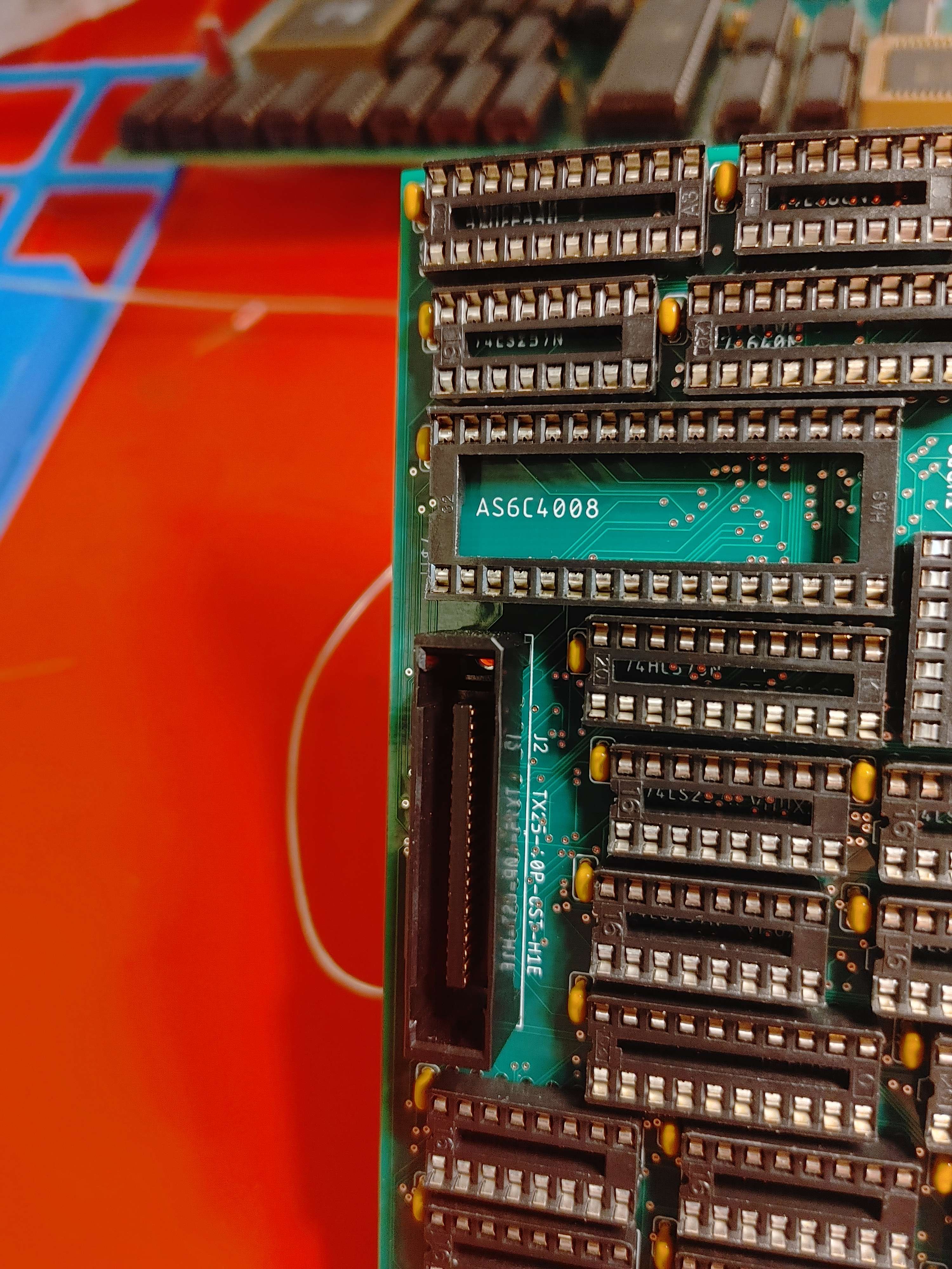
Step 12: Mezzanine Connector (Audio Side)
- TX24-40P-12ST-H1E
- It is IMPORTANT that the beveled corner is on the top left to mate with the A/V board (assuming controller ports are oriented downward)
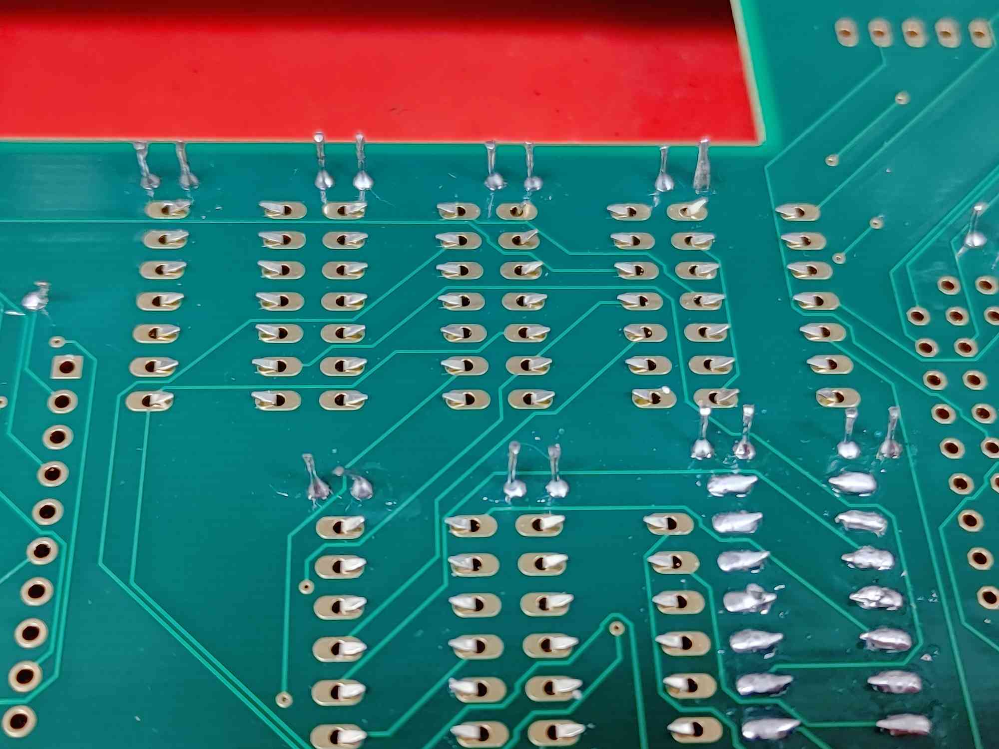
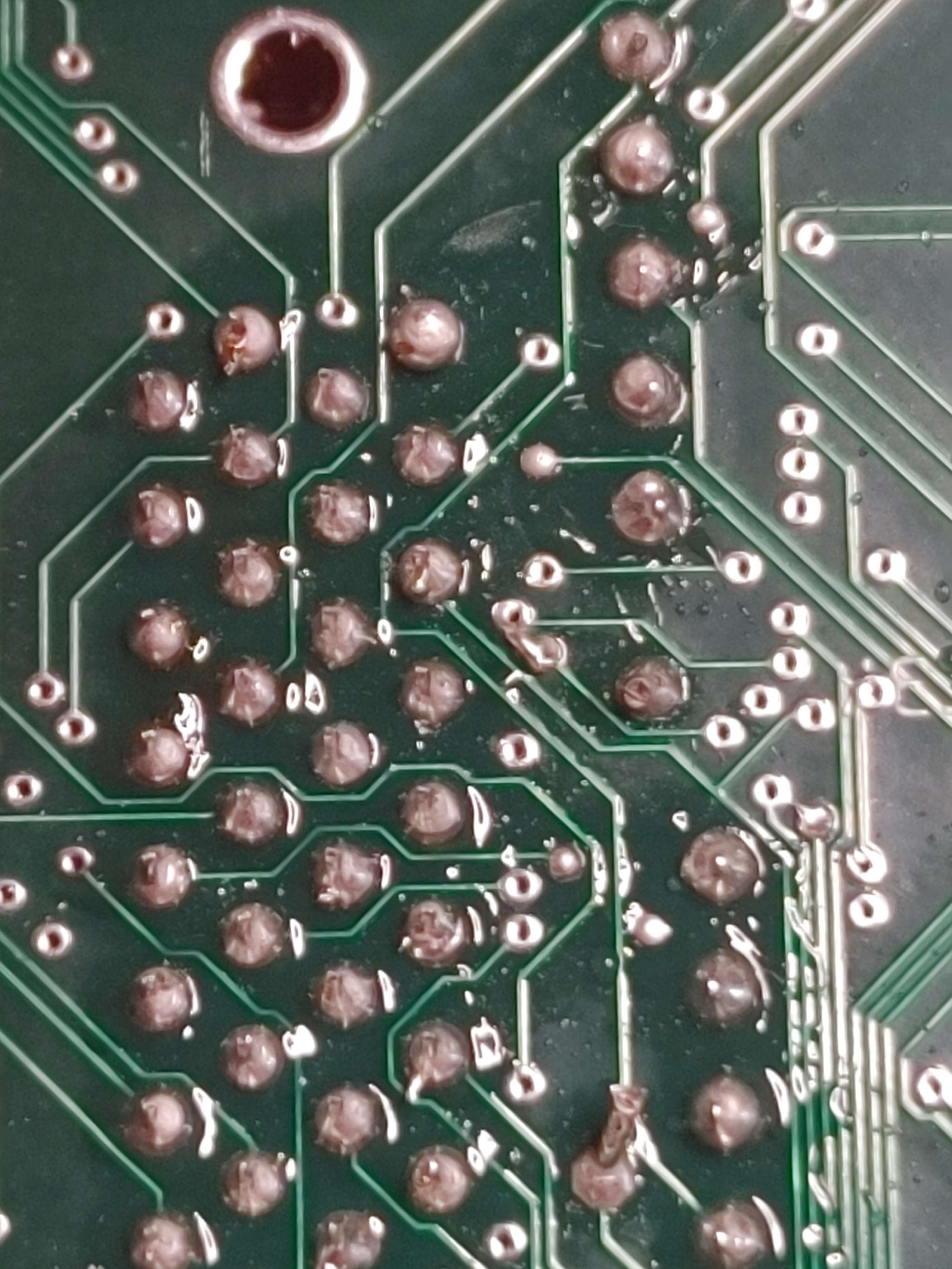
- There are a lot of vias on this board, so be careful not to short any of this connector's small pins to a via.
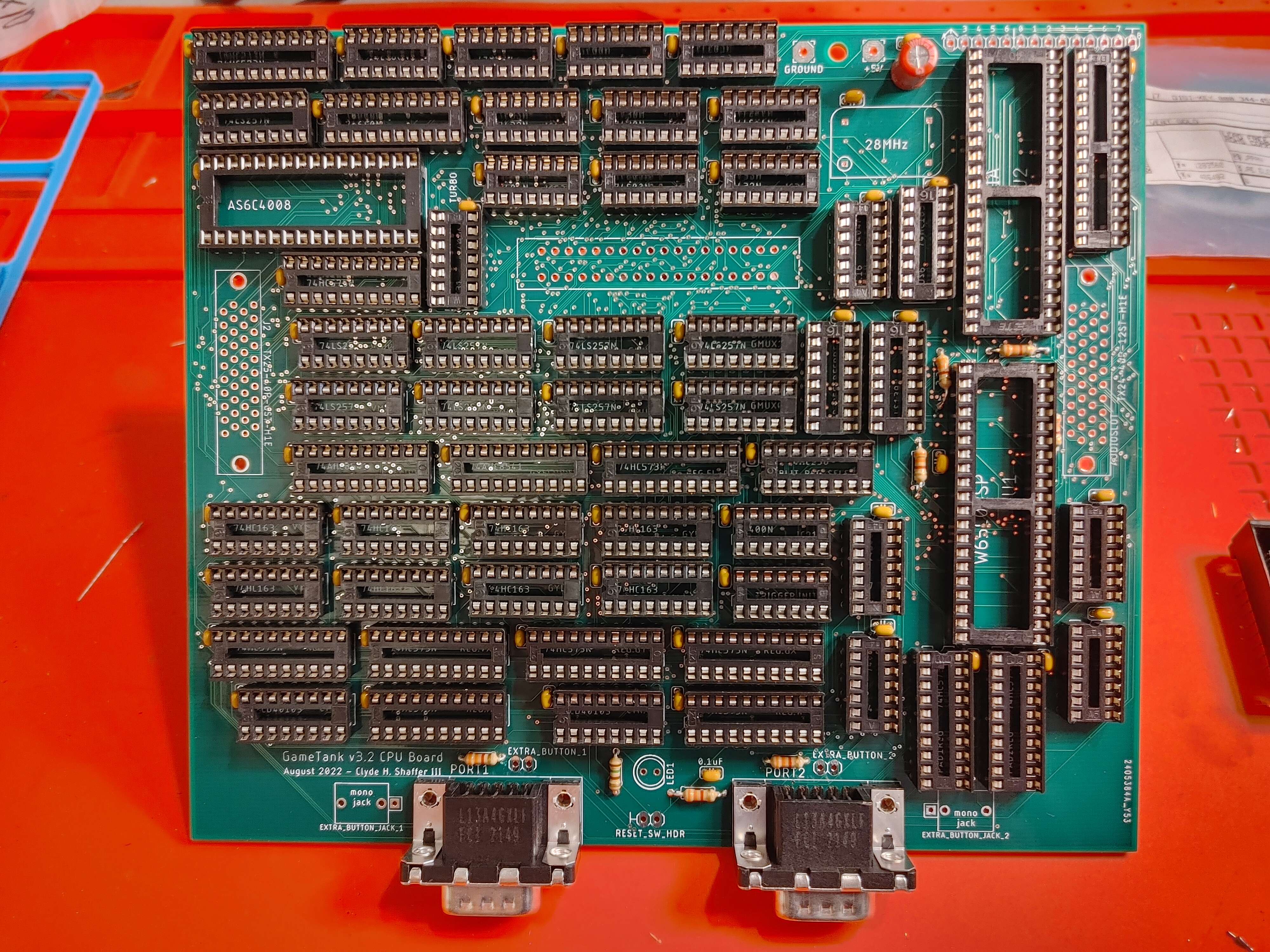
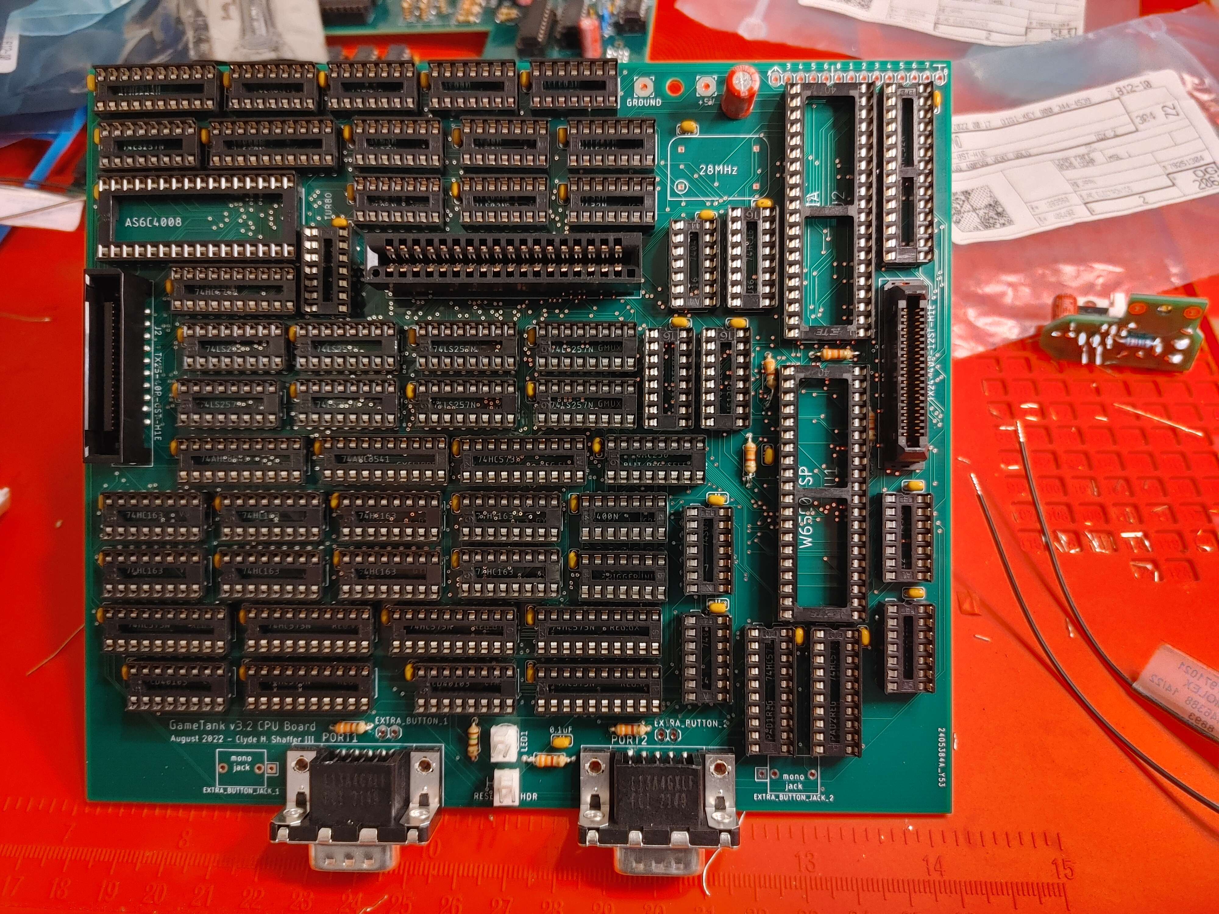
Step 14: Cartridge Slot
- 36 pin edge connector, with 0.1 inch spacing
- The connection is not symmetrical (don't put carts in backwards) but the connector itself is symmetrical and can be installed in either direction.
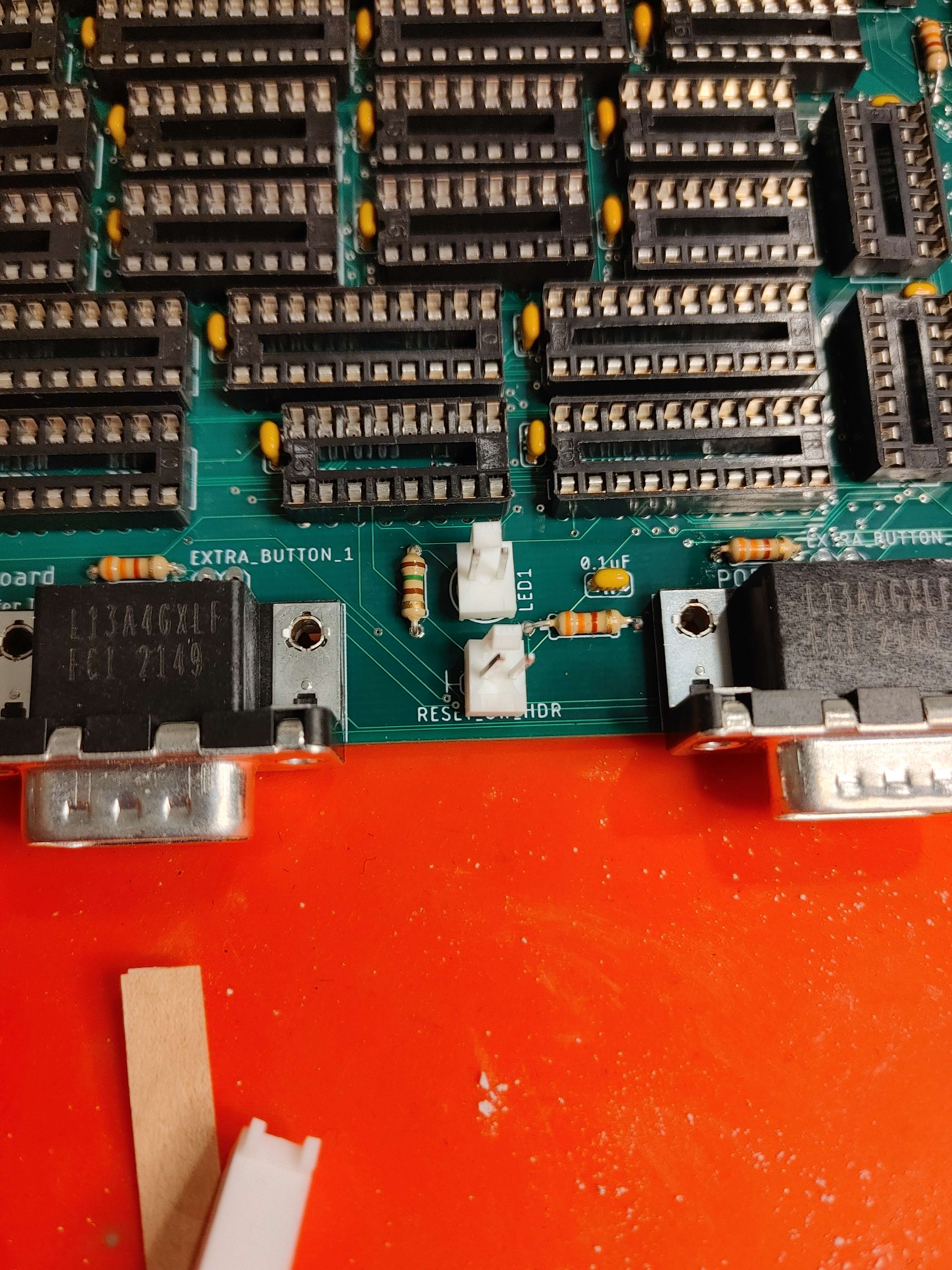
Step 15: Molex Headers
- Two locking molex 1x2 header pins
- For RESET_SW_HDR the orientation should't matter.
- For LED1 just make sure that when you attach the opposite connector to the LED wire, that the flat side of the circle aligns with the minus side of the connection.
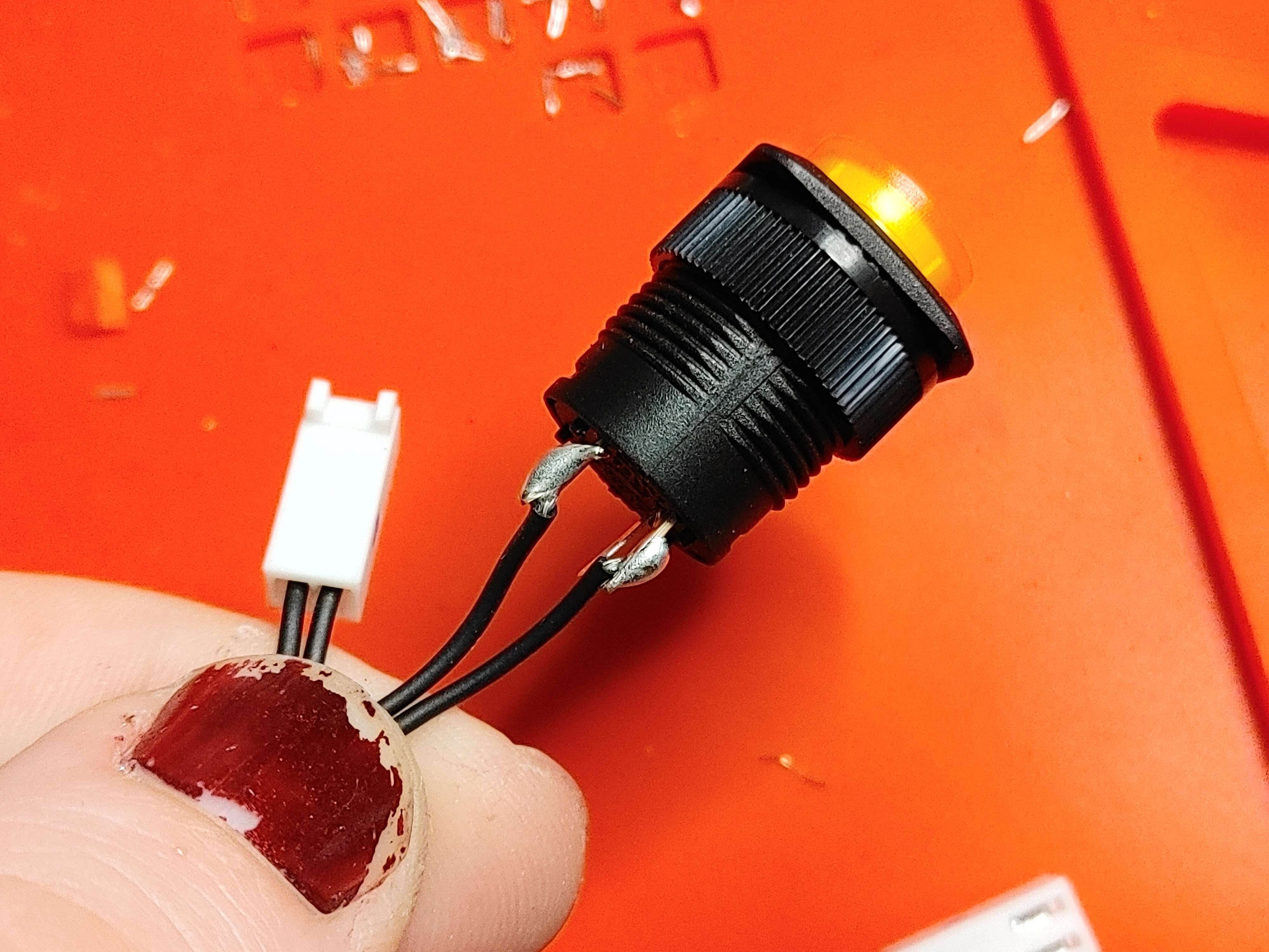
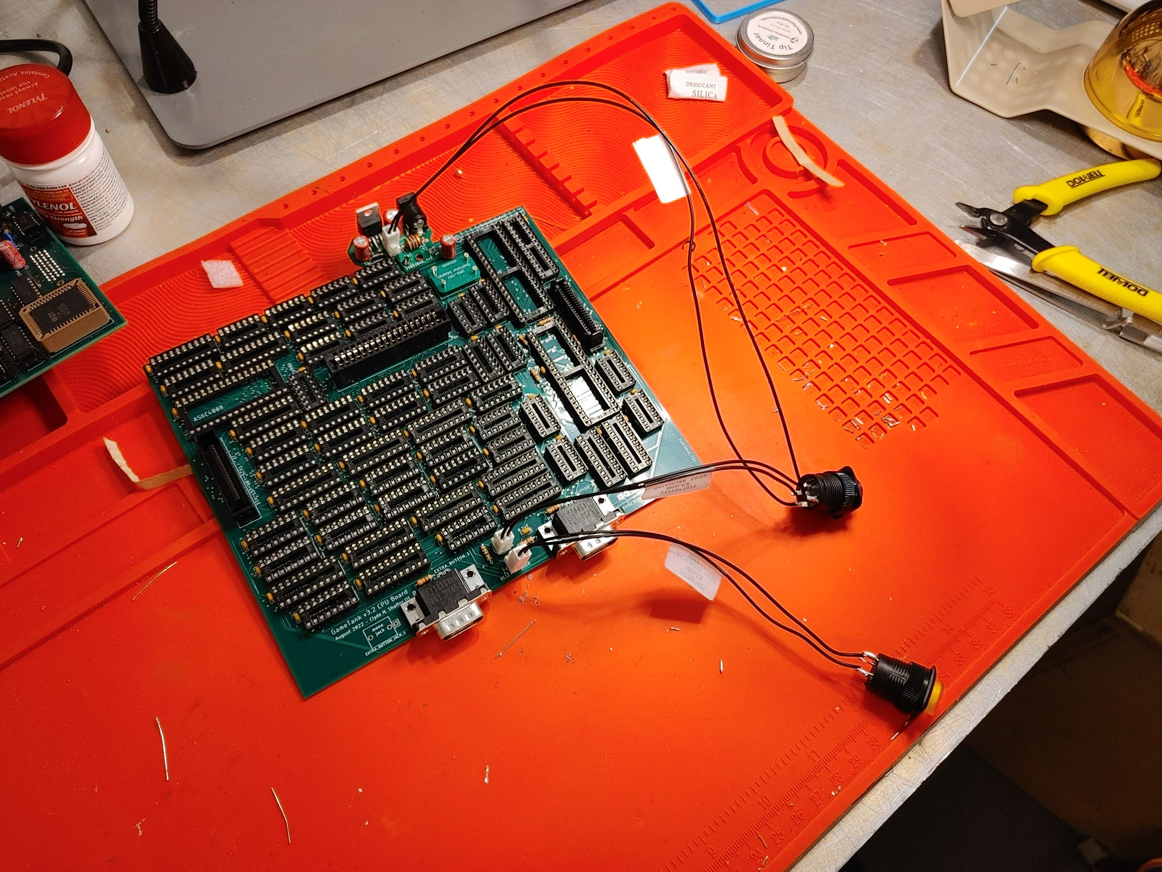
Step 16: Reset Button Wiring
- 1 x shorter wire with molex plug attached
- 1 x Yellow button (momentary switch)
- Solder one of the wires with a molex plug to the switching pins
- The plus and minus pins aren't needed for this button.
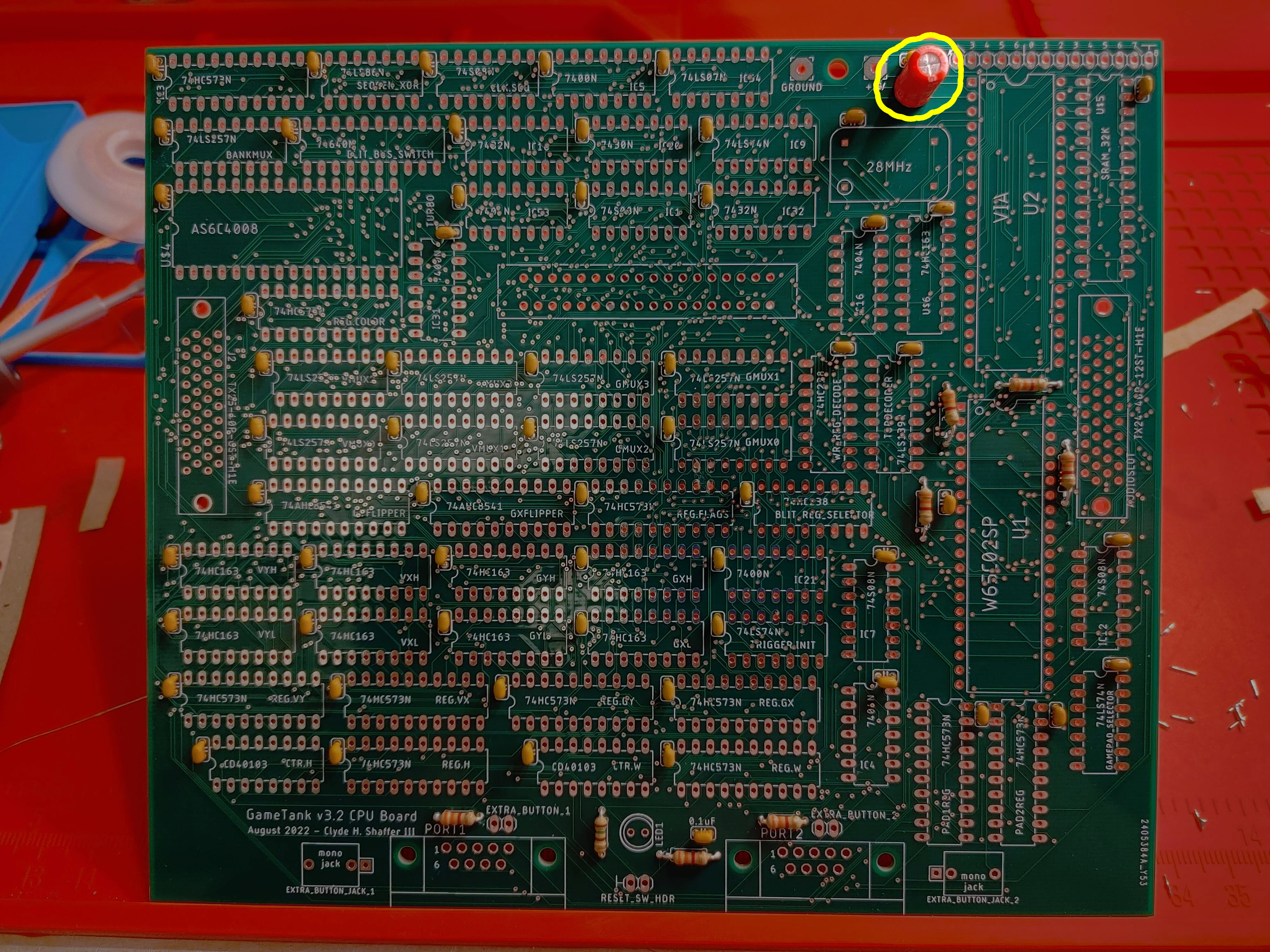
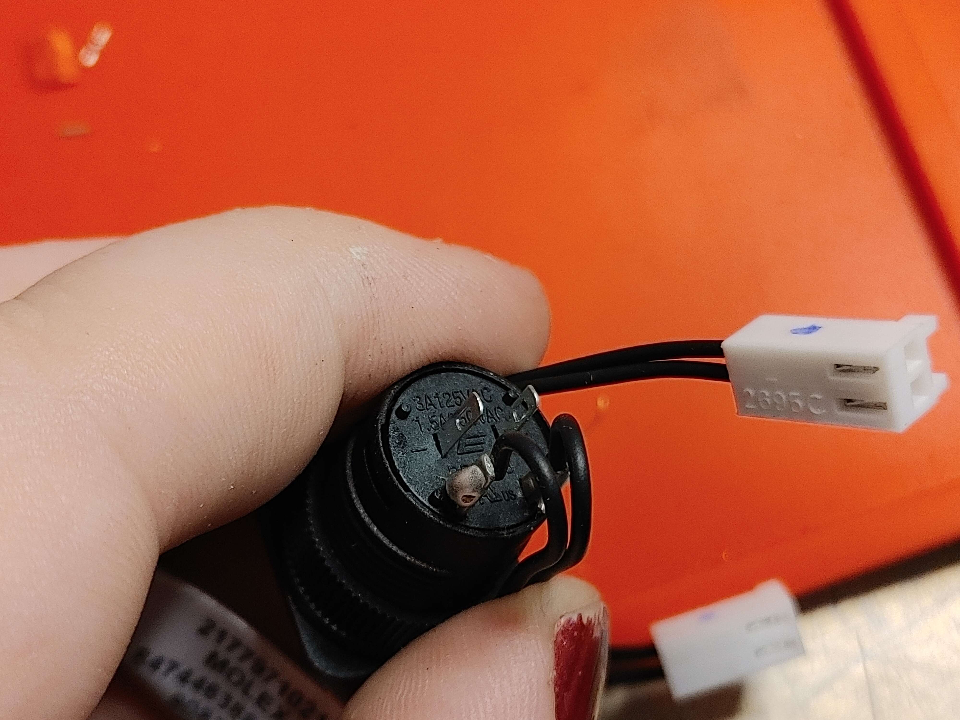
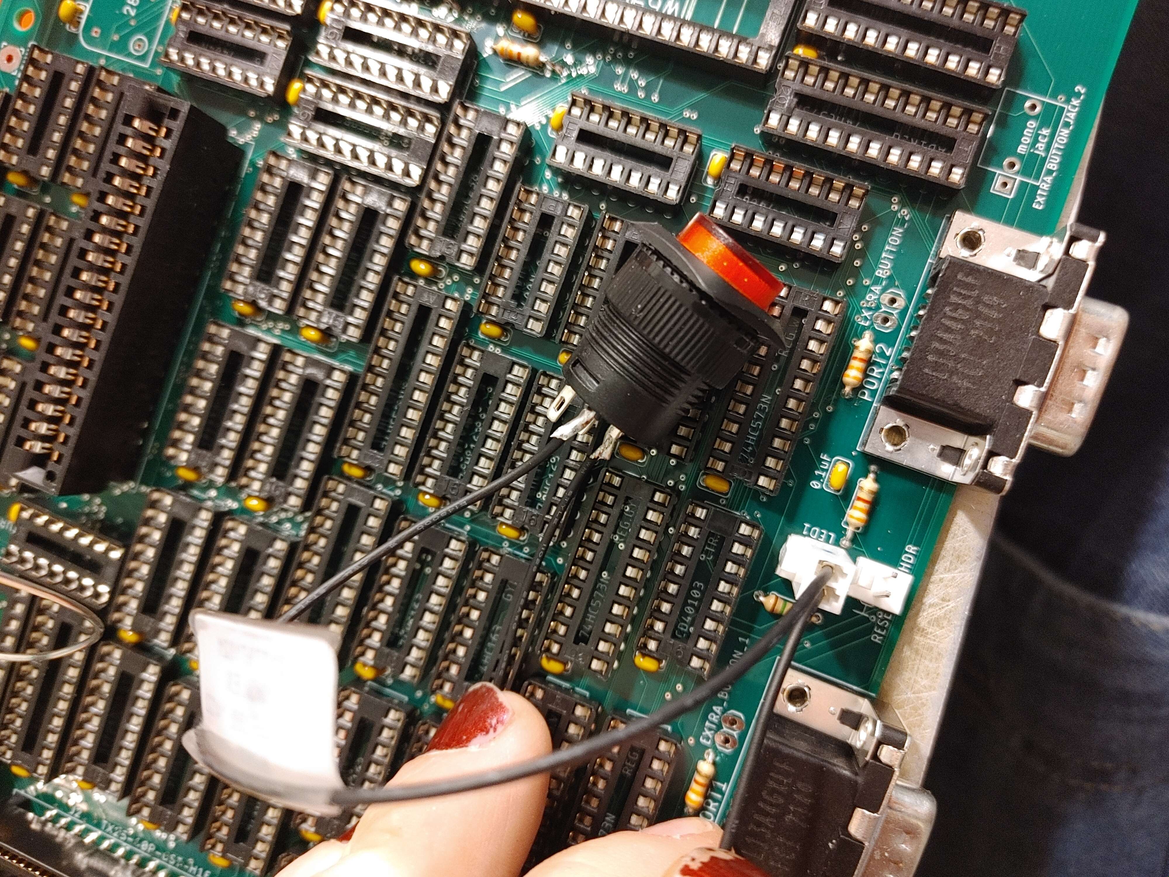
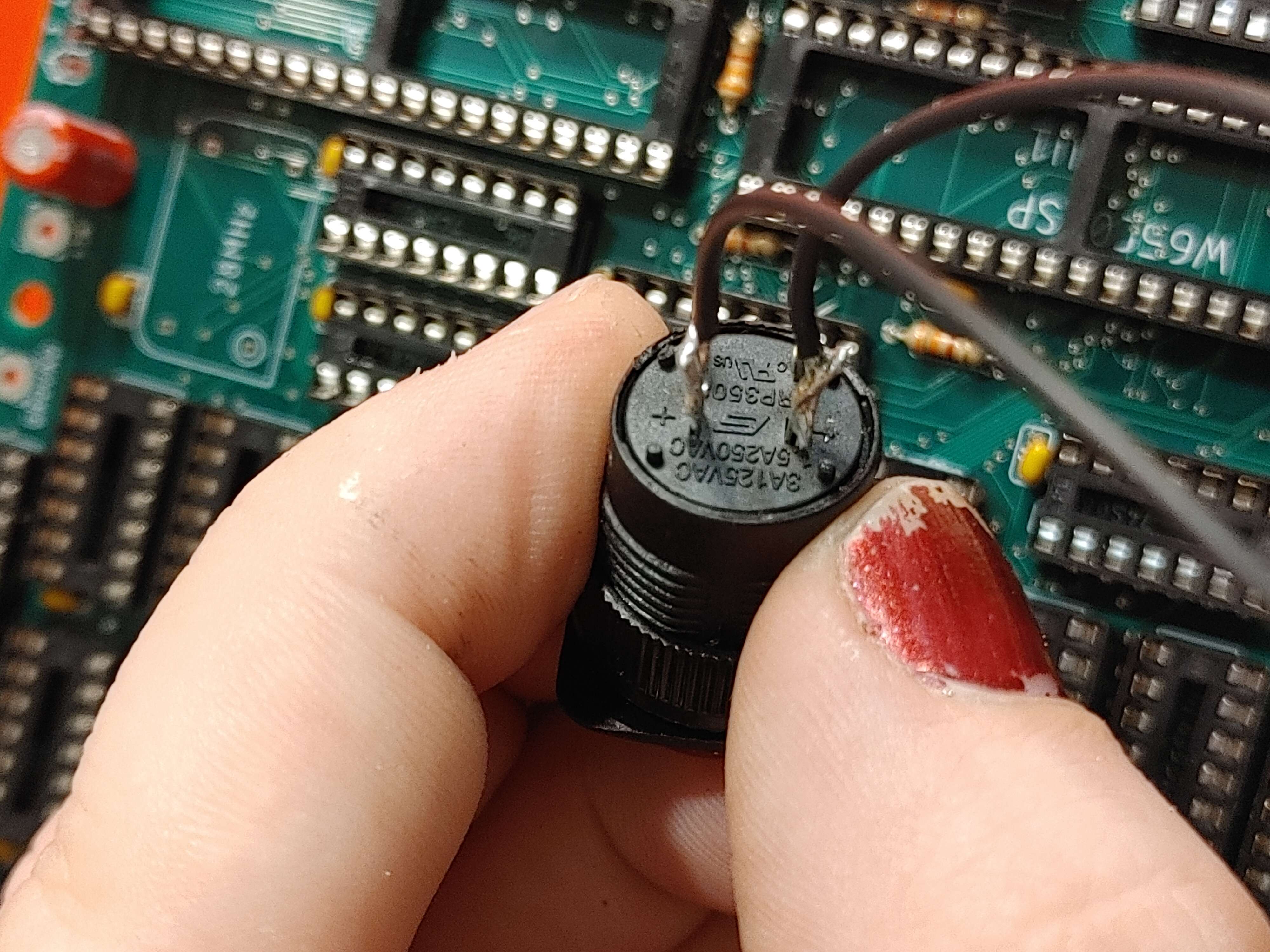
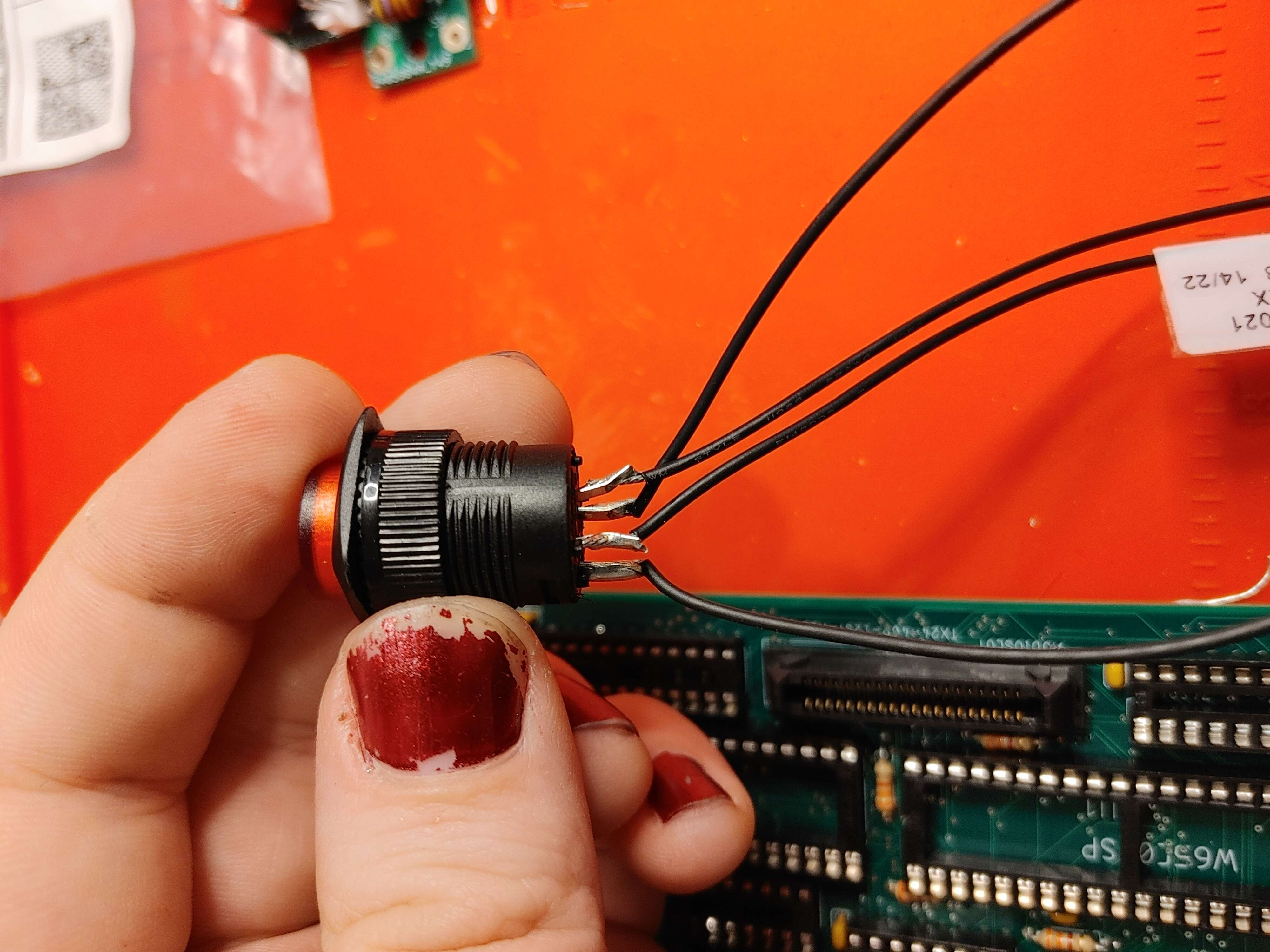
Step 17: Power Button Wiring
- 1 x shorter wire with molex plug attached
- 1 x longer wire with molex plug attached
- 1 x Red button (on/off toggle)
- The shorter wire connects to the plus and minus LED terminals
- Check the orientation of the header from the earlier Molex Headers step. Ensure that the minus side connects to the grounded flat side of the circular LED marker.
- The longer wire is used for the other two pins (switch) and its polarity doesn't really matter
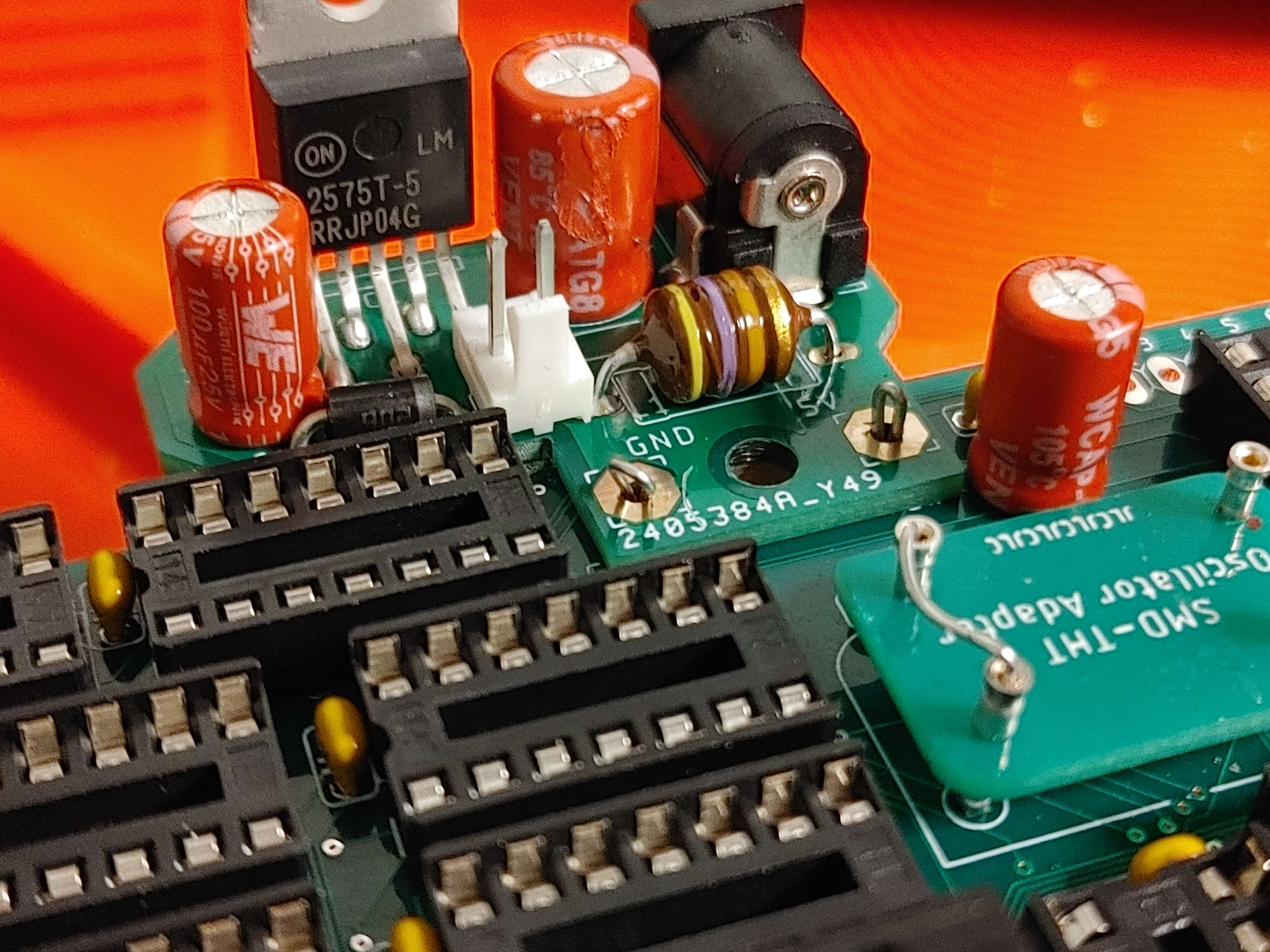
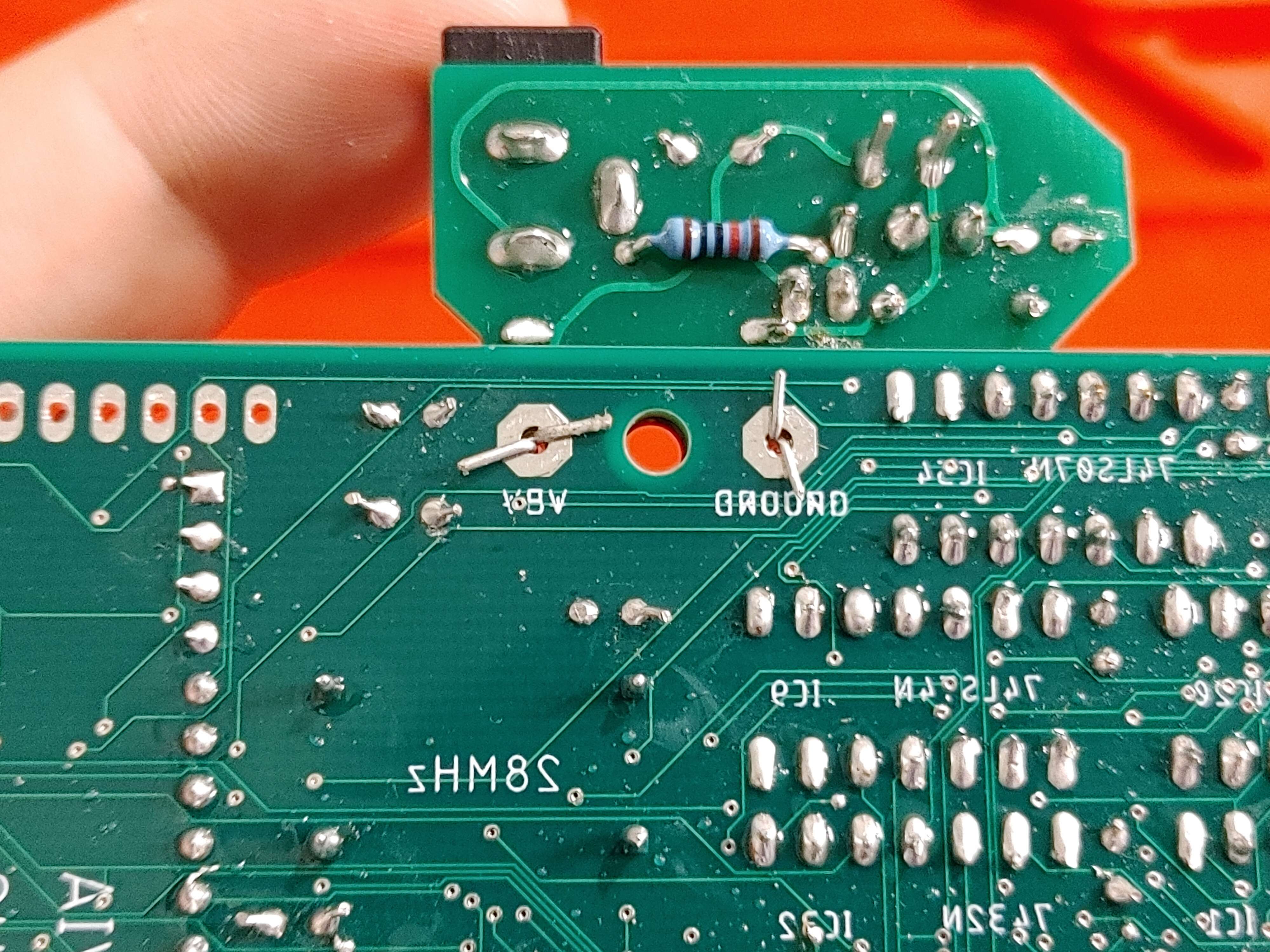
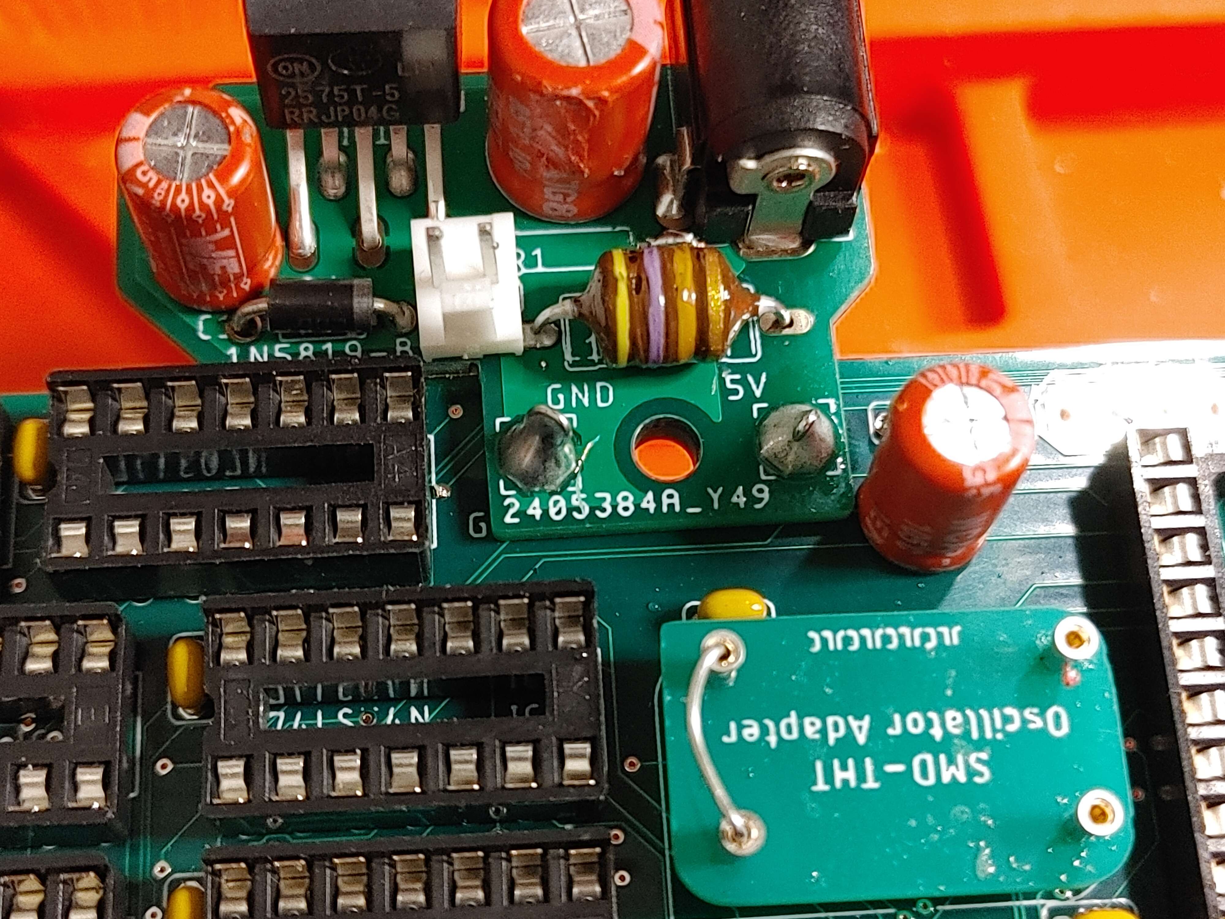
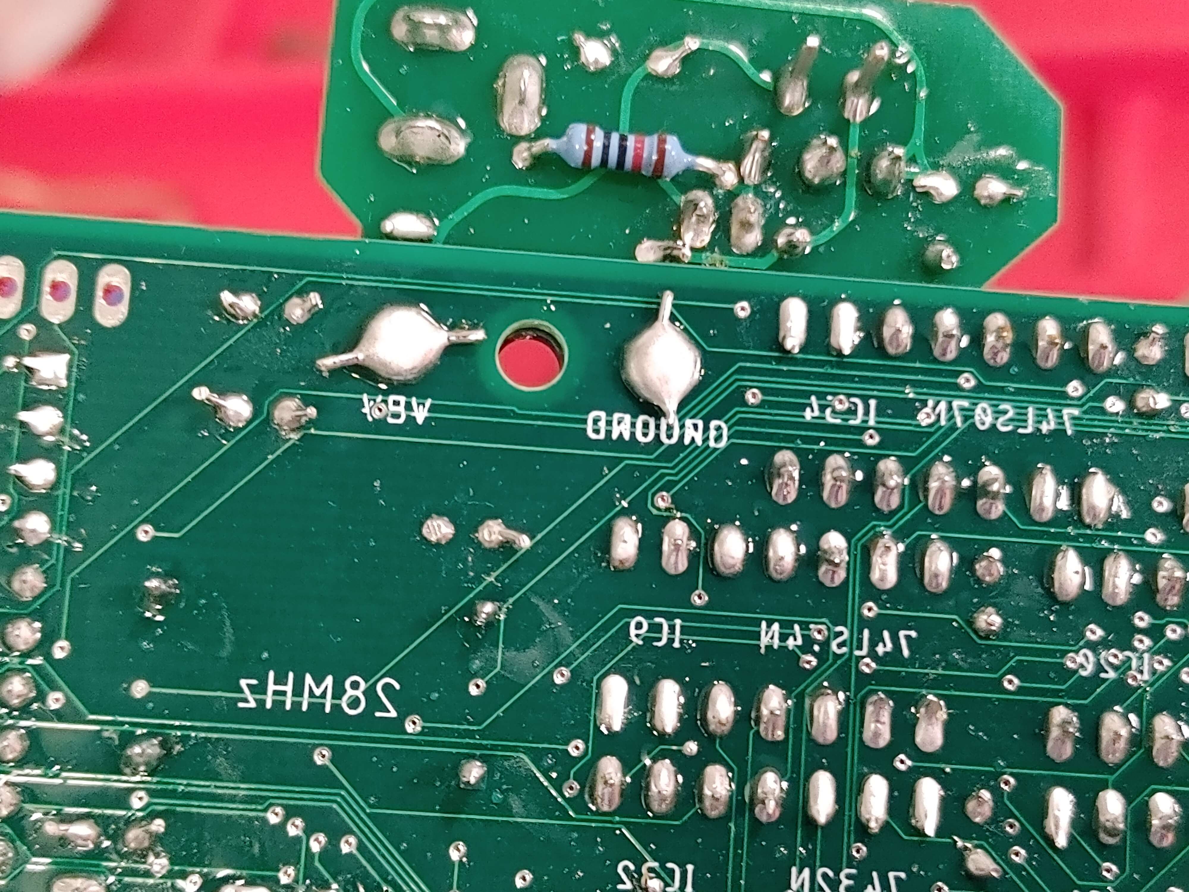
Step 18: Mount Power Board
- 1 x Power Board (assembled with separate instructions)
- 2 x trimmed resistor leads from earlier
- Align GND and 5V pads and put folded resistor leads through
- bend the folded leads outward on the underside so they stay put like binder clips
- Solder this in place
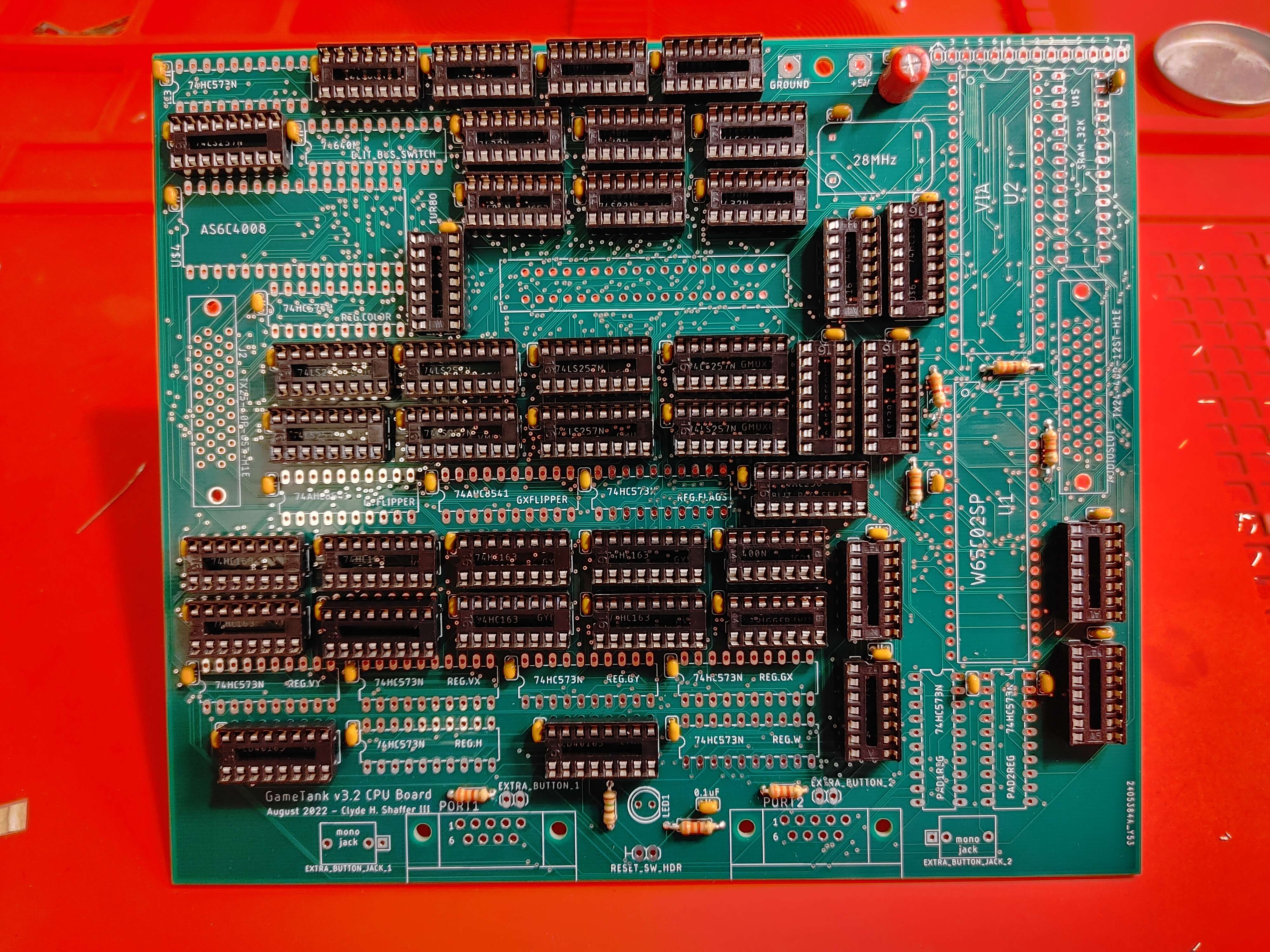
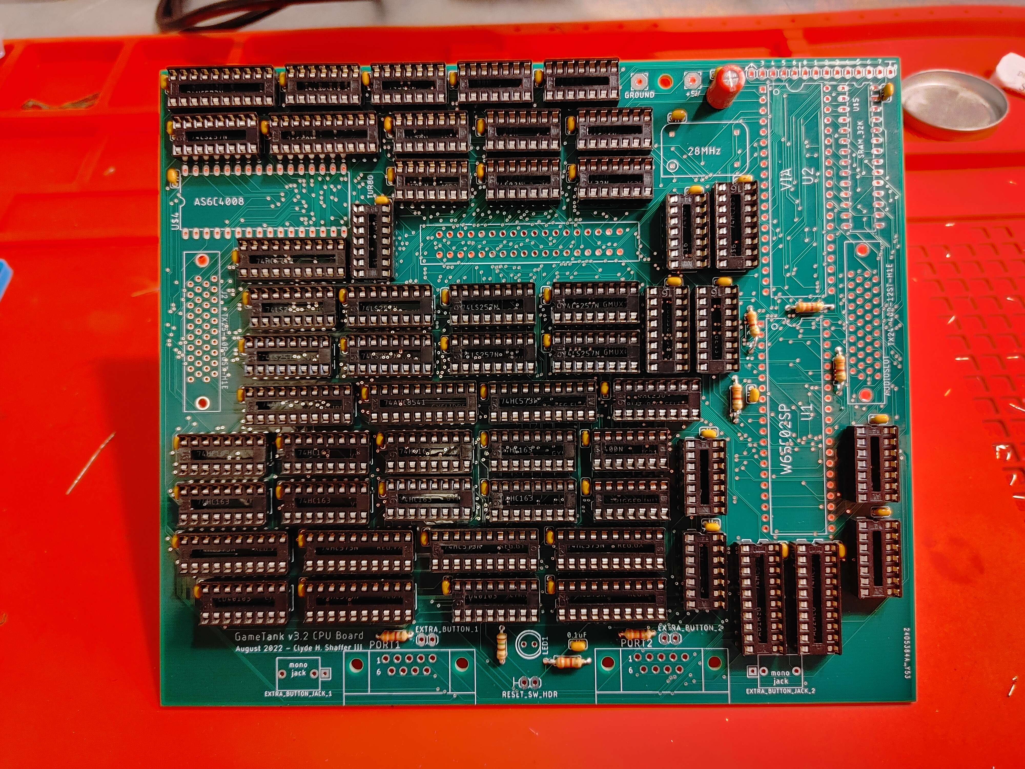
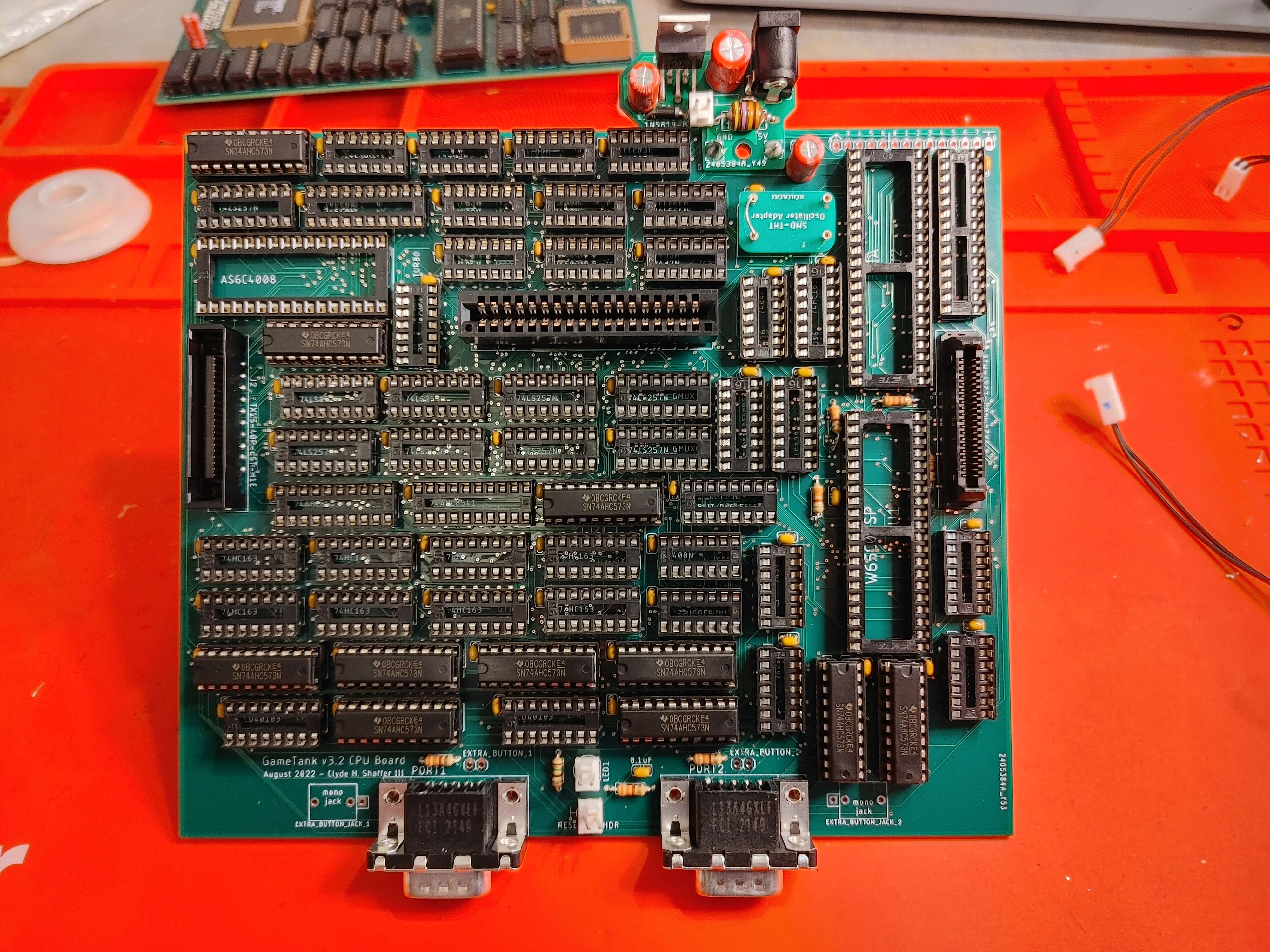
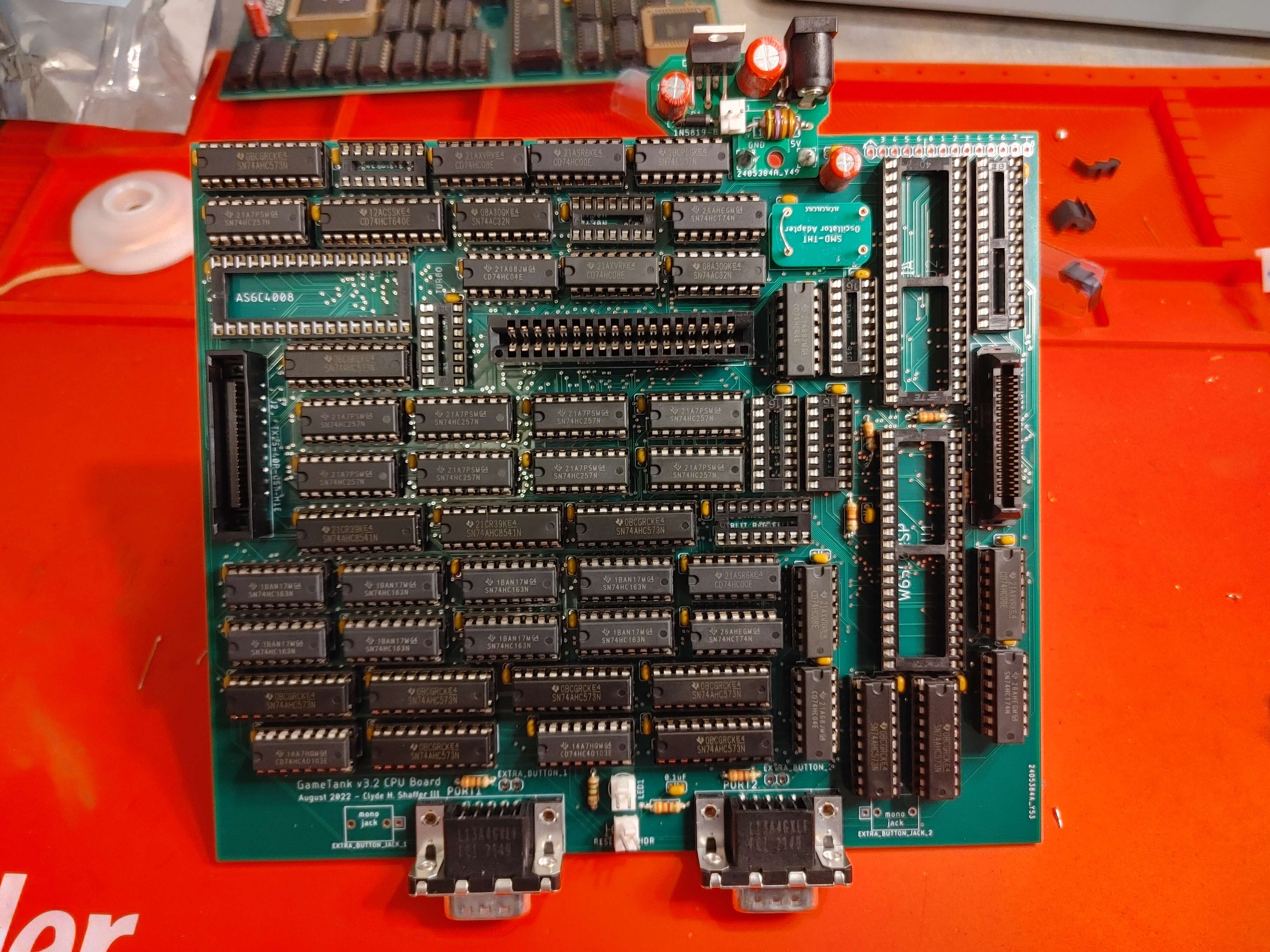
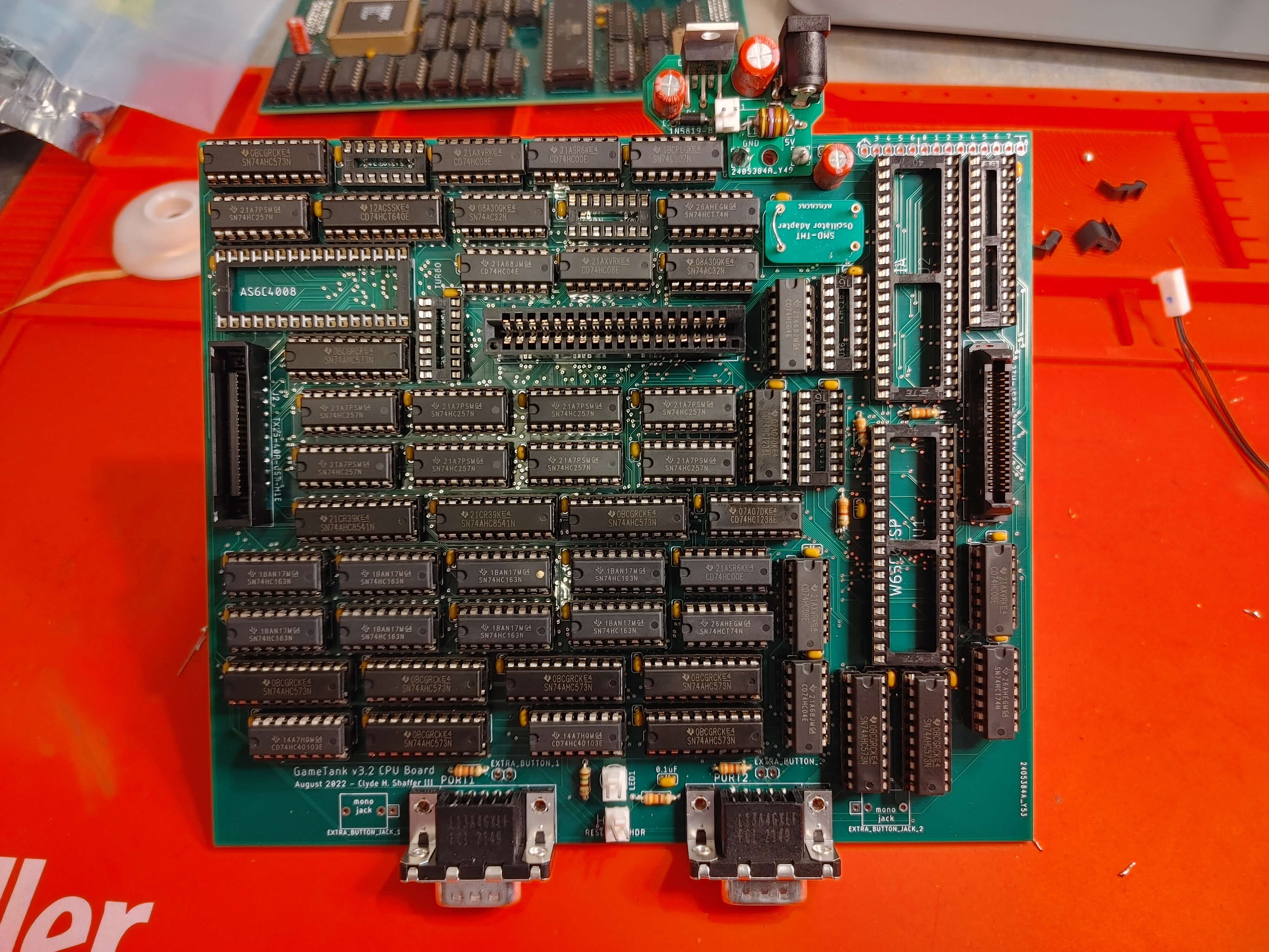
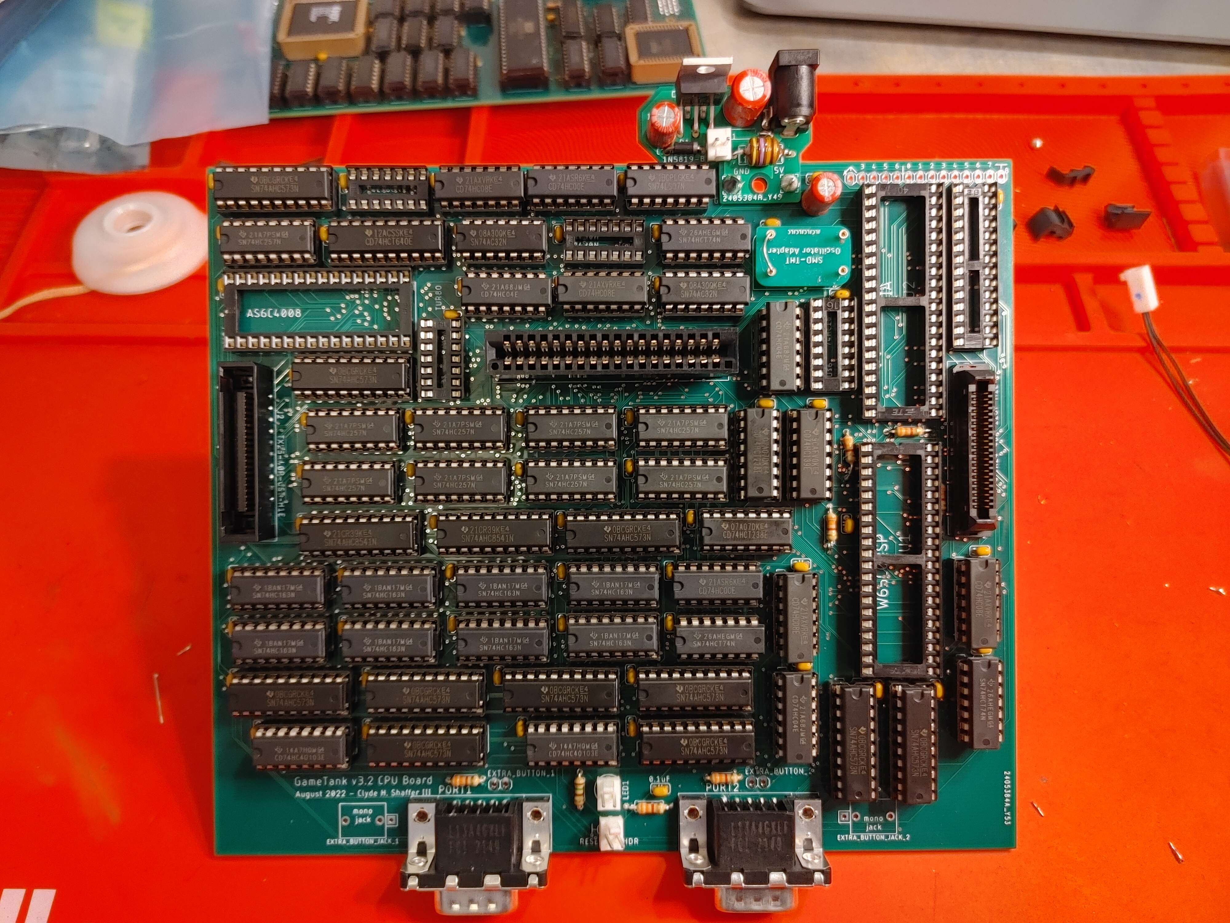
Step 20: 11 x 74HC573
- Depending on the market, the HCT or AHC versions might be easier to get. These will work fine.
- The text on the chip might end in an N or an E. This denotes what factory they came from and doesn't matter here.
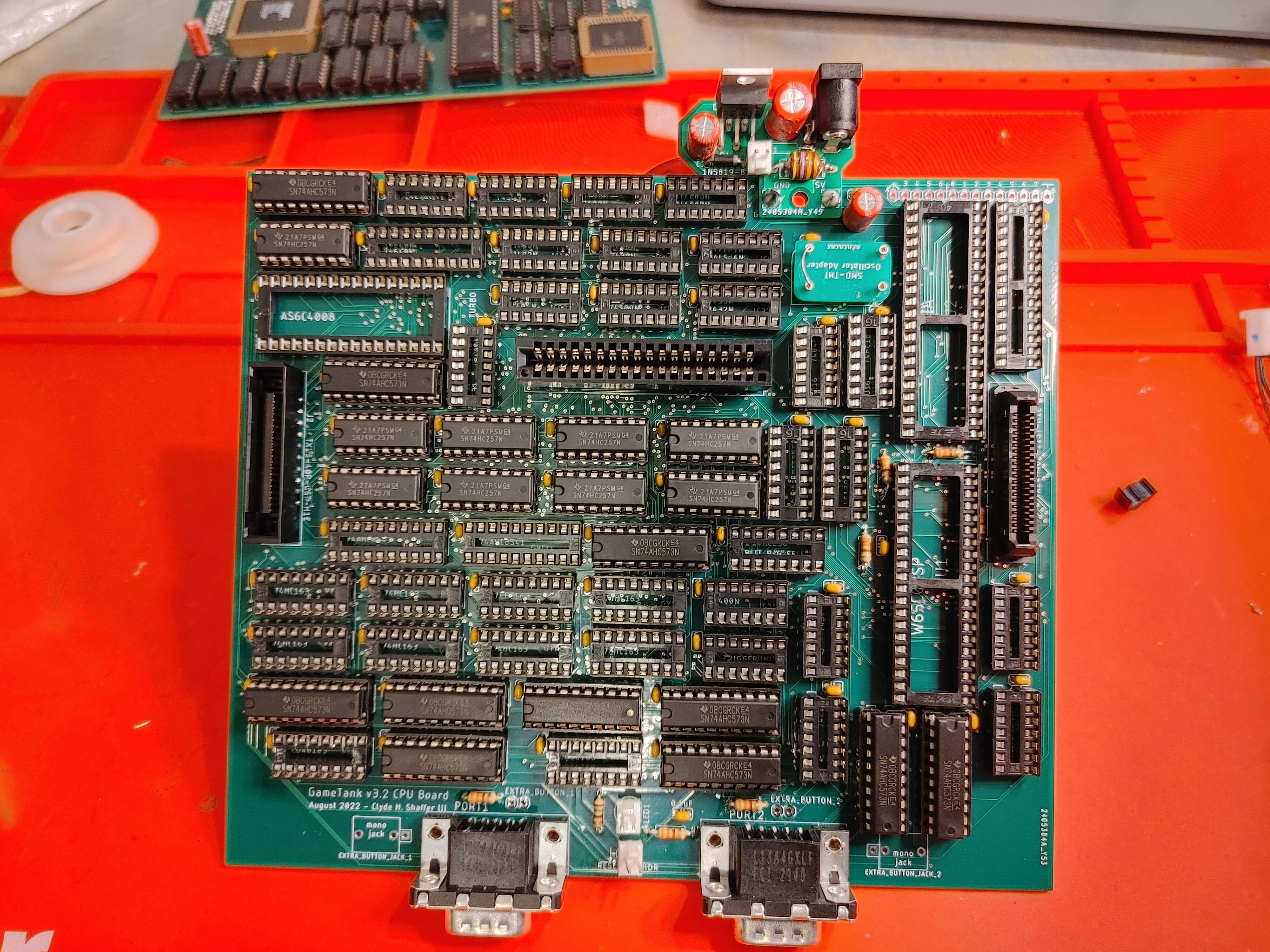
Step 21: 9 x 74HC257
- Depending on the market, the HCT or AHC versions might be easier to get. These will work fine.
- The text on the chip might end in an N or an E. This denotes what factory they came from and doesn't matter here.
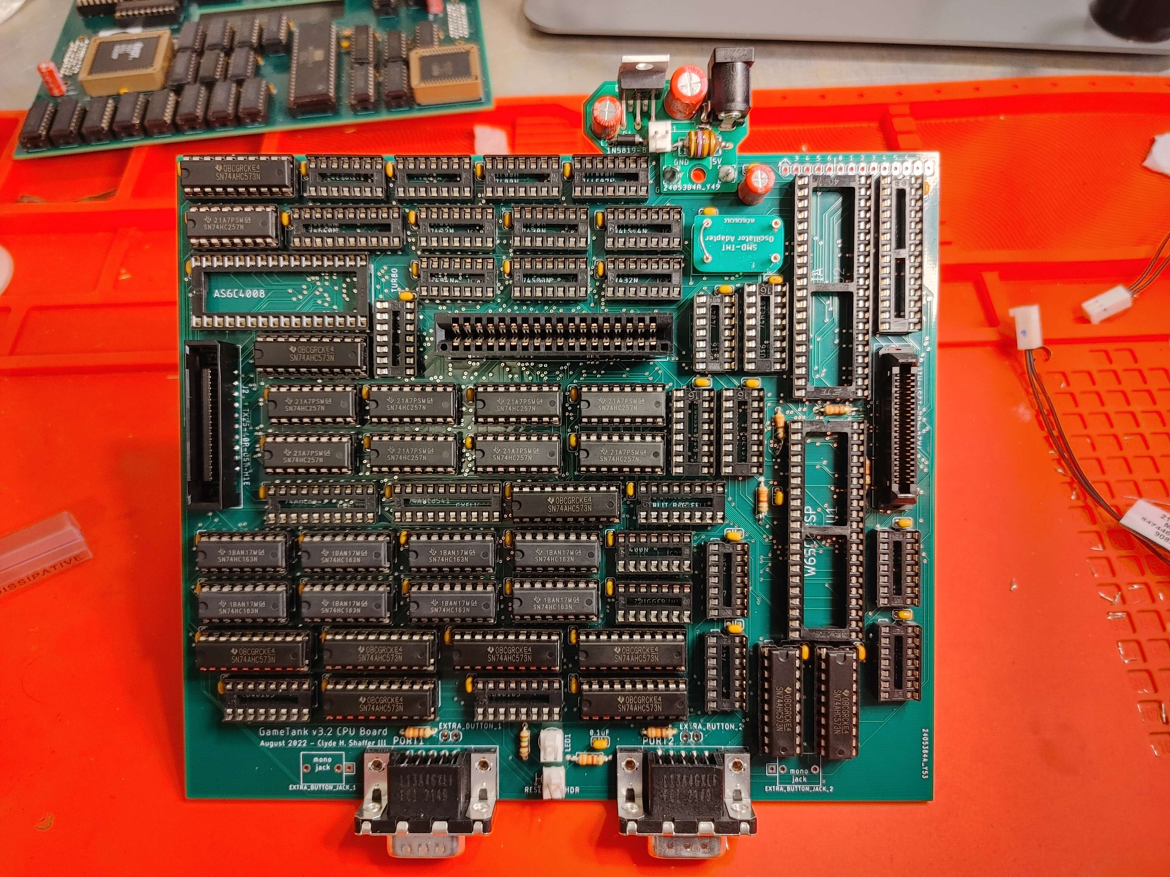
Step 22: 8 x 74HC163
- Depending on the market, the HCT or AHC versions might be easier to get. These will work fine.
- The text on the chip might end in an N or an E. This denotes what factory they came from and doesn't matter here.
Step 23: 4 x 74HC08
- Depending on the market, the HCT or AHC versions might be easier to get. These will work fine.
- The text on the chip might end in an N or an E. This denotes what factory they came from and doesn't matter here.
Step 24: 3 x 74HC04
- Depending on the market, the HCT or AHC versions might be easier to get. These will work fine.
- The text on the chip might end in an N or an E. This denotes what factory they came from and doesn't matter here.
Step 25: 3 x 74HC74
- Depending on the market, the HCT or AHC versions might be easier to get. These will work fine.
- The text on the chip might end in an N or an E. This denotes what factory they came from and doesn't matter here.
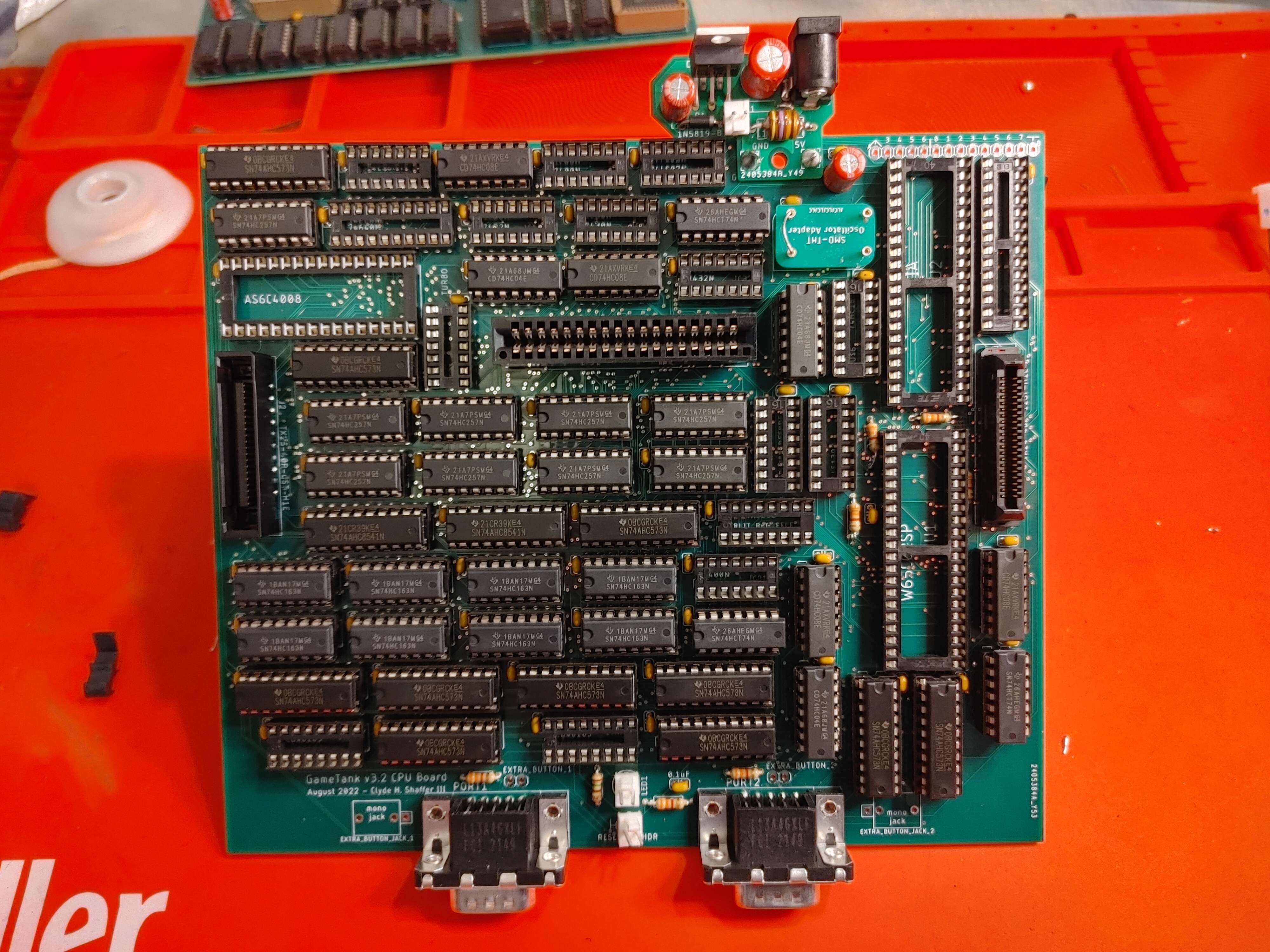
Step 26: 2 x 74HC8541
- Depending on the market, the HCT or AHC versions might be easier to get. These will work fine.
- The text on the chip might end in an N or an E. This denotes what factory they came from and doesn't matter here.
Step 27: 2 x 74HC32
- Depending on the market, the HCT or AHC versions might be easier to get. These will work fine.
- The text on the chip might end in an N or an E. This denotes what factory they came from and doesn't matter here.
Step 28: 2 x 74HC40103
- Depending on the market, the HCT or AHC versions might be easier to get. These will work fine.
- The text on the chip might end in an N or an E. This denotes what factory they came from and doesn't matter here.
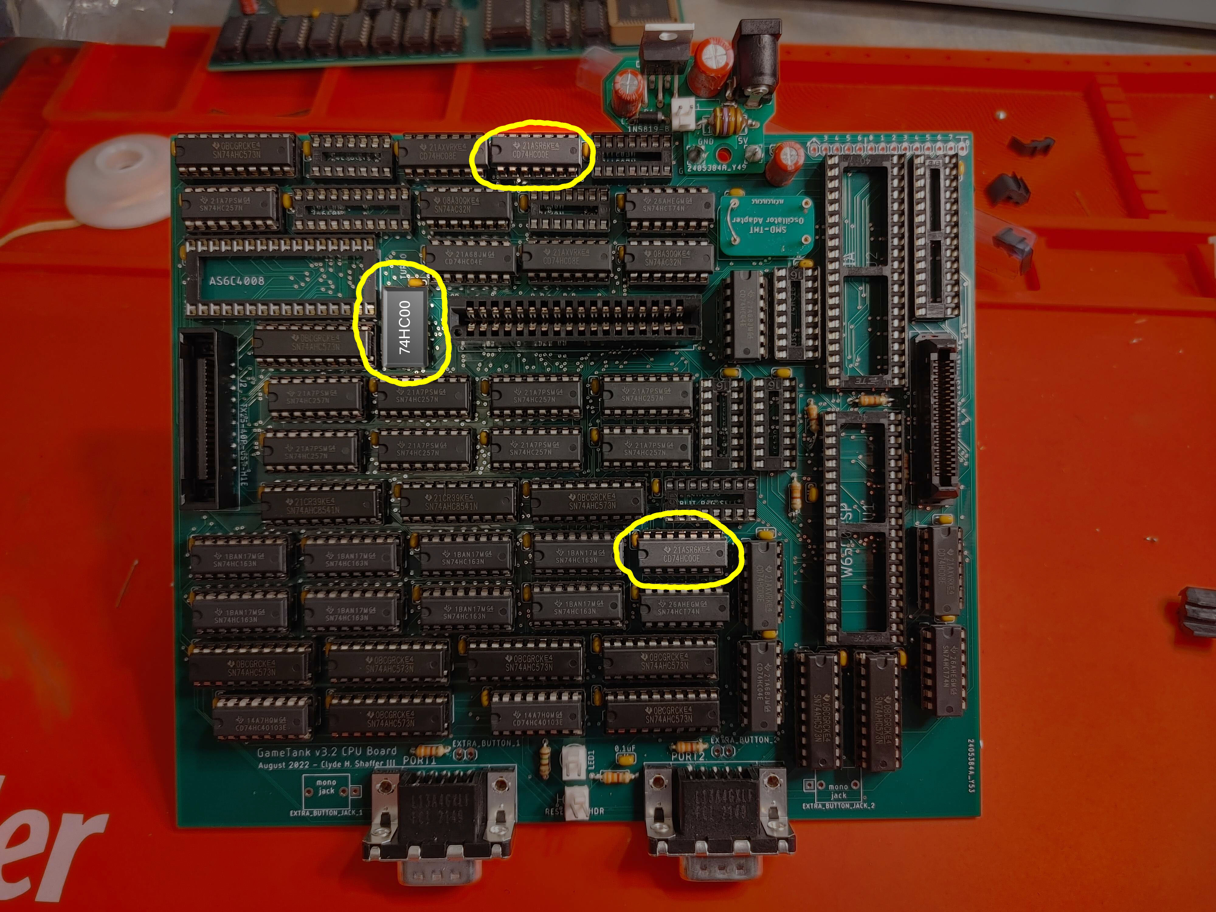
Step 29: 3 x 74HC00
- At the time these photos were taken, one 74HC00 was missing. It will be digitally added to the photo for this step, please imagine it is with us in sucessive photos if it hasn't been edited in.
- Depending on the market, the HCT or AHC versions might be easier to get. These will work fine.
- The text on the chip might end in an N or an E. This denotes what factory they came from and doesn't matter here.
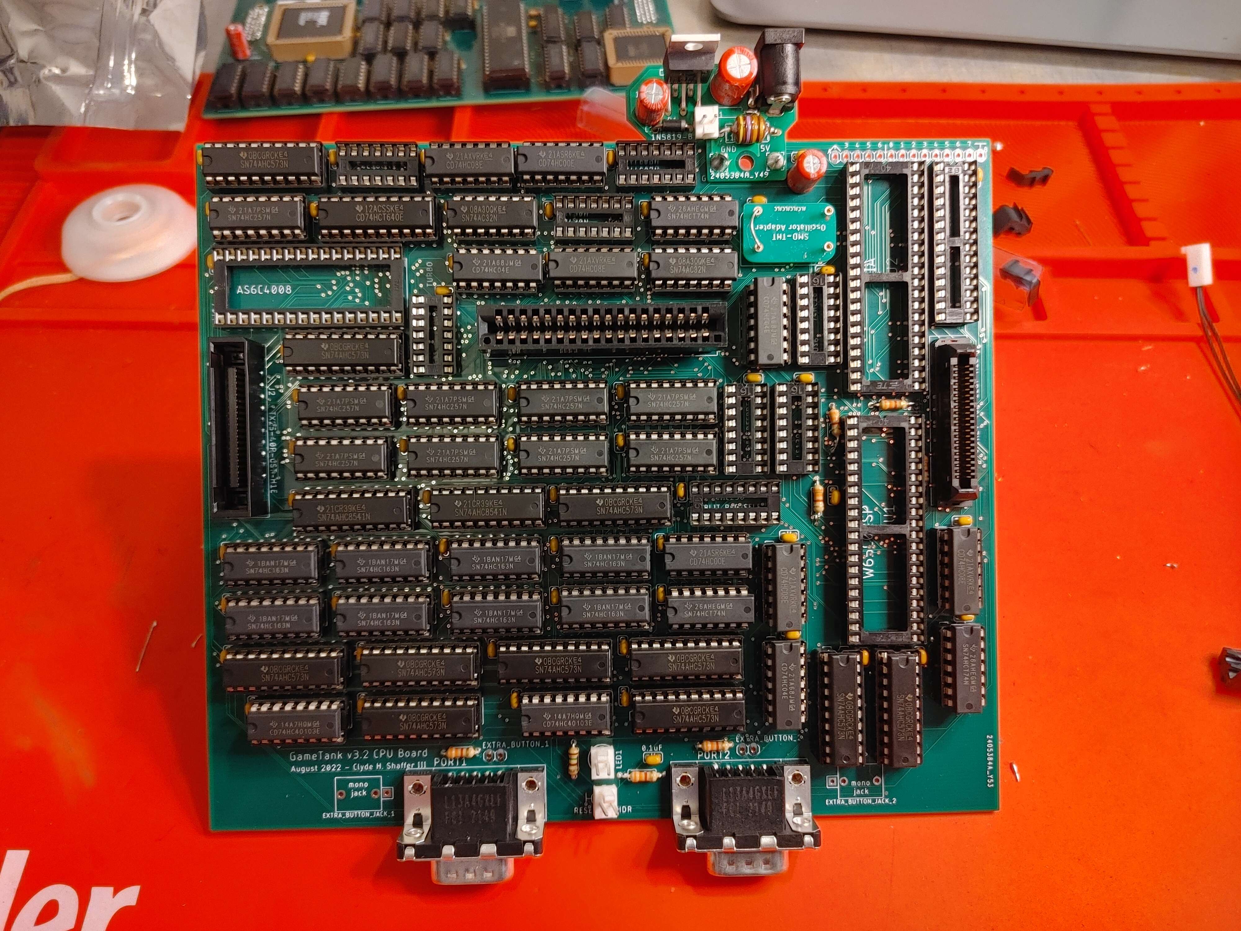
Step 30: 1 x 74HC640
- Depending on the market, the HCT or AHC versions might be easier to get. These will work fine.
- The text on the chip might end in an N or an E. This denotes what factory they came from and doesn't matter here.
Step 31: 1 x 74LS07
- The 07 is an open-drain buffer and should SPECIFICALLY be the LS version.
- The text on the chip might end in an N or an E. This denotes what factory they came from and doesn't matter here.
Step 32: 2 x 74HC238
- Depending on the market, the HCT or AHC versions might be easier to get. These will work fine.
- The text on the chip might end in an N or an E. This denotes what factory they came from and doesn't matter here.
Step 33: 1 x 74HC139
- Depending on the market, the HCT or AHC versions might be easier to get. These will work fine.
- The text on the chip might end in an N or an E. This denotes what factory they came from and doesn't matter here.
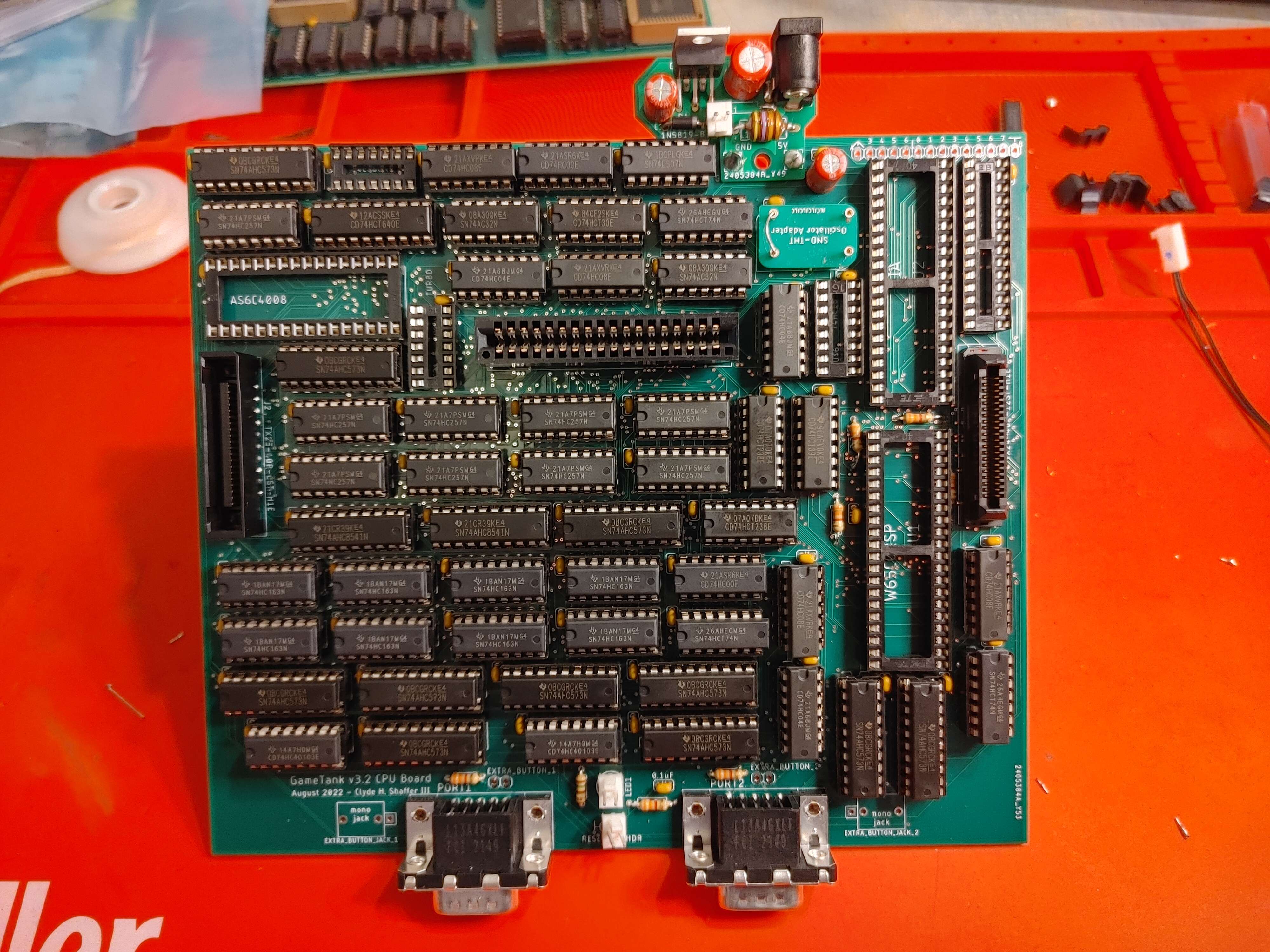
Step 34: 1 x 74HC30
- Depending on the market, the HCT or AHC versions might be easier to get. These will work fine.
- The text on the chip might end in an N or an E. This denotes what factory they came from and doesn't matter here.
Step 35: 1 x 74HC86
- Depending on the market, the HCT or AHC versions might be easier to get. These will work fine.
- The text on the chip might end in an N or an E. This denotes what factory they came from and doesn't matter here.
Step 38: 1 x 74AC161
- Should SPECIFICALLY be the AC version
- Goes in a spot labeled U$6 that may be labeled 74163 despite us using a 161 here
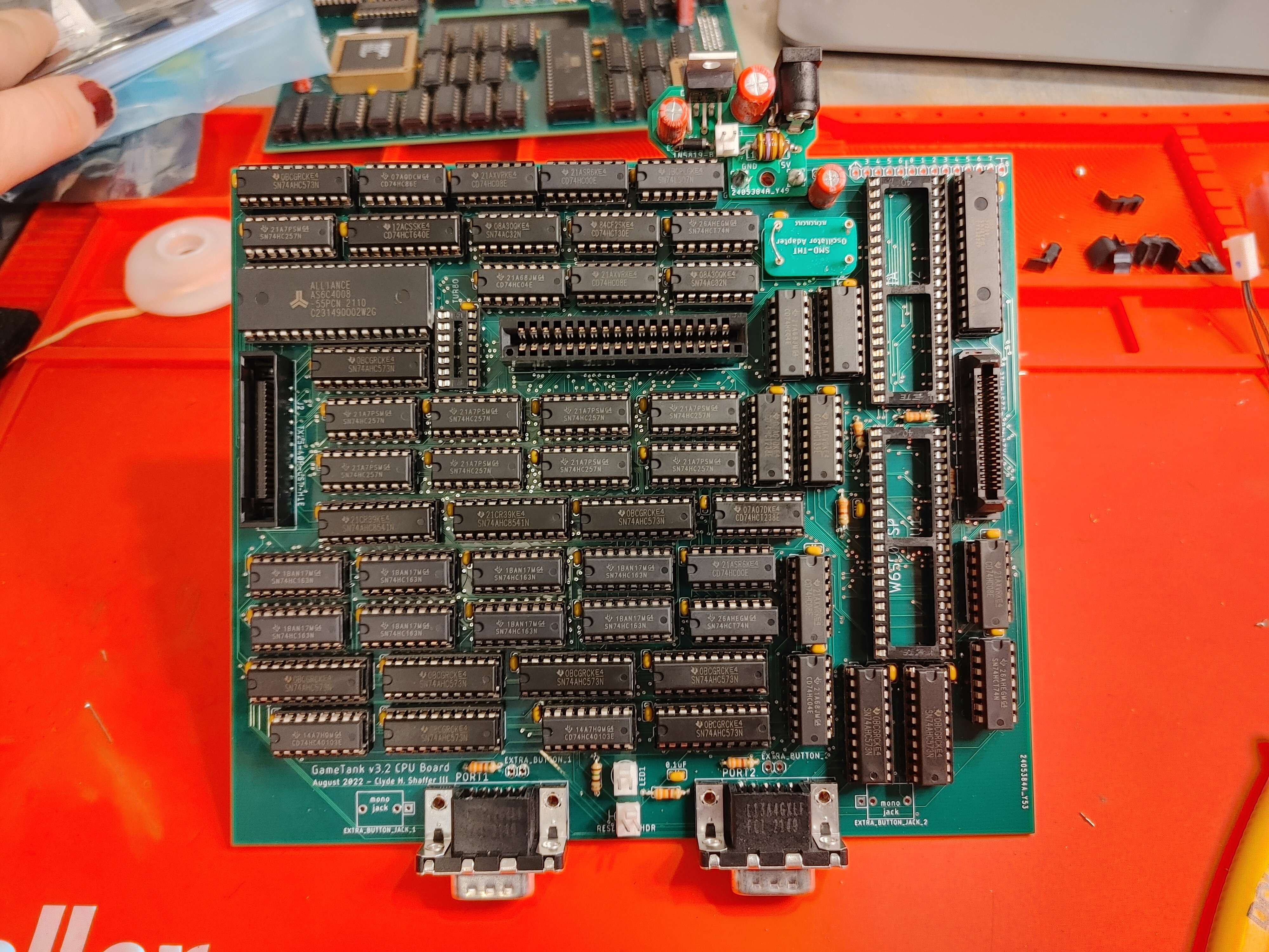
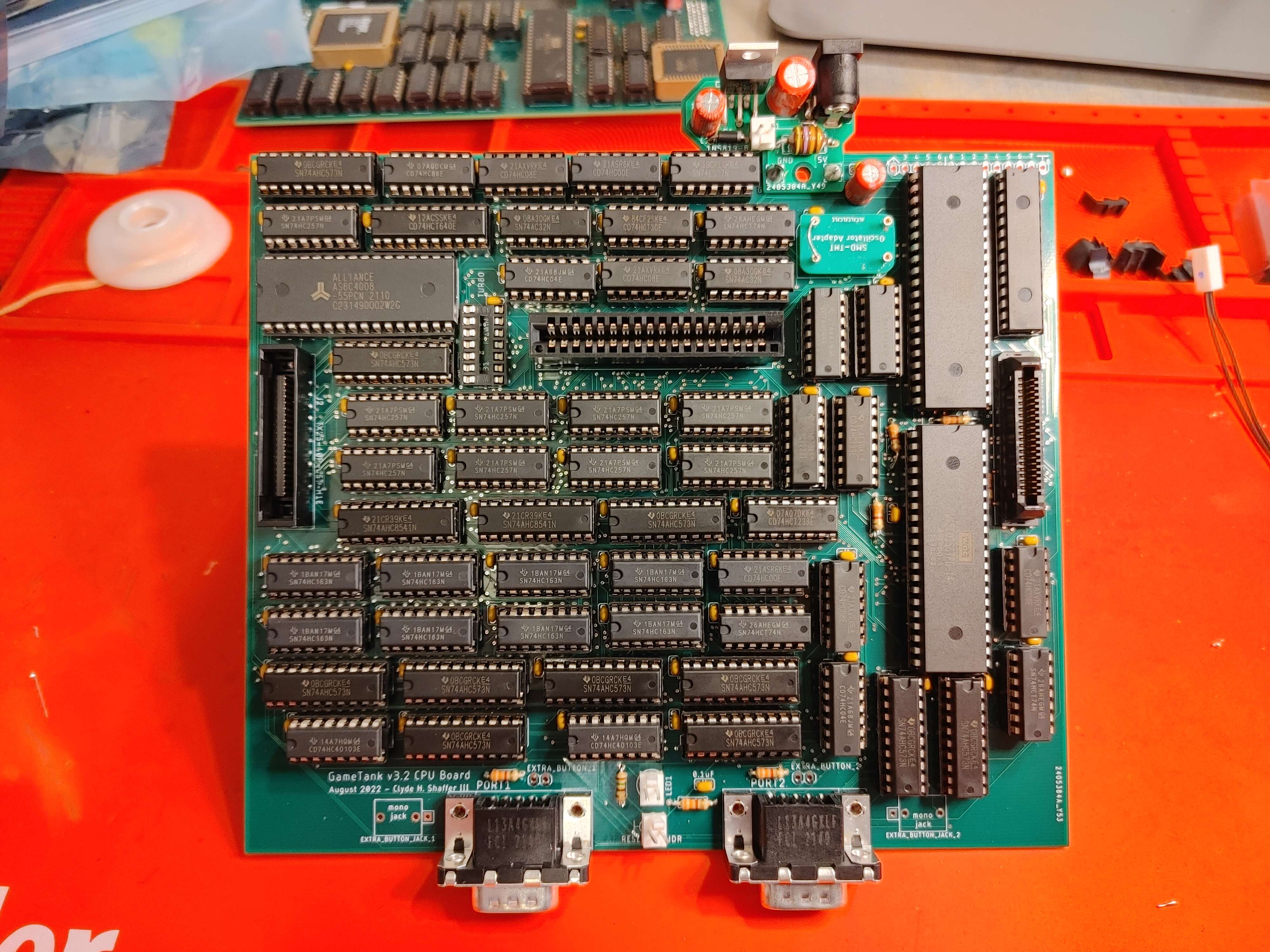
Step 39: 1 x W65C02S
- The CPU
- This board is designed around Western Design Center's "modern" 6502 and probably won't work with old stock NMOS chips.
Step 40: 1 x W65C22S
- The Versatile Interface Adapter
- If you've already build the A/V board then all that's left to do is to connect the two together and wrangle it into a case!