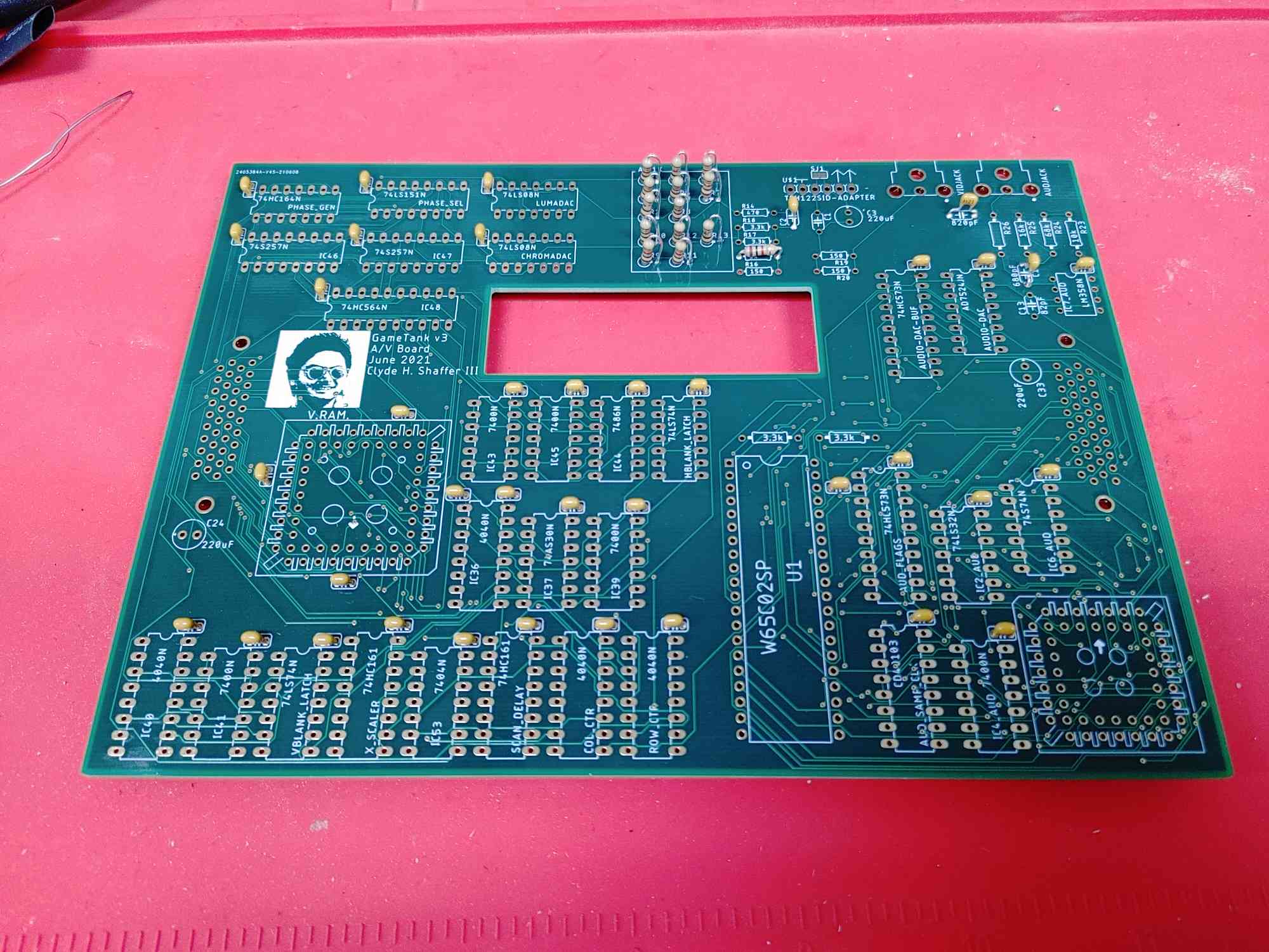
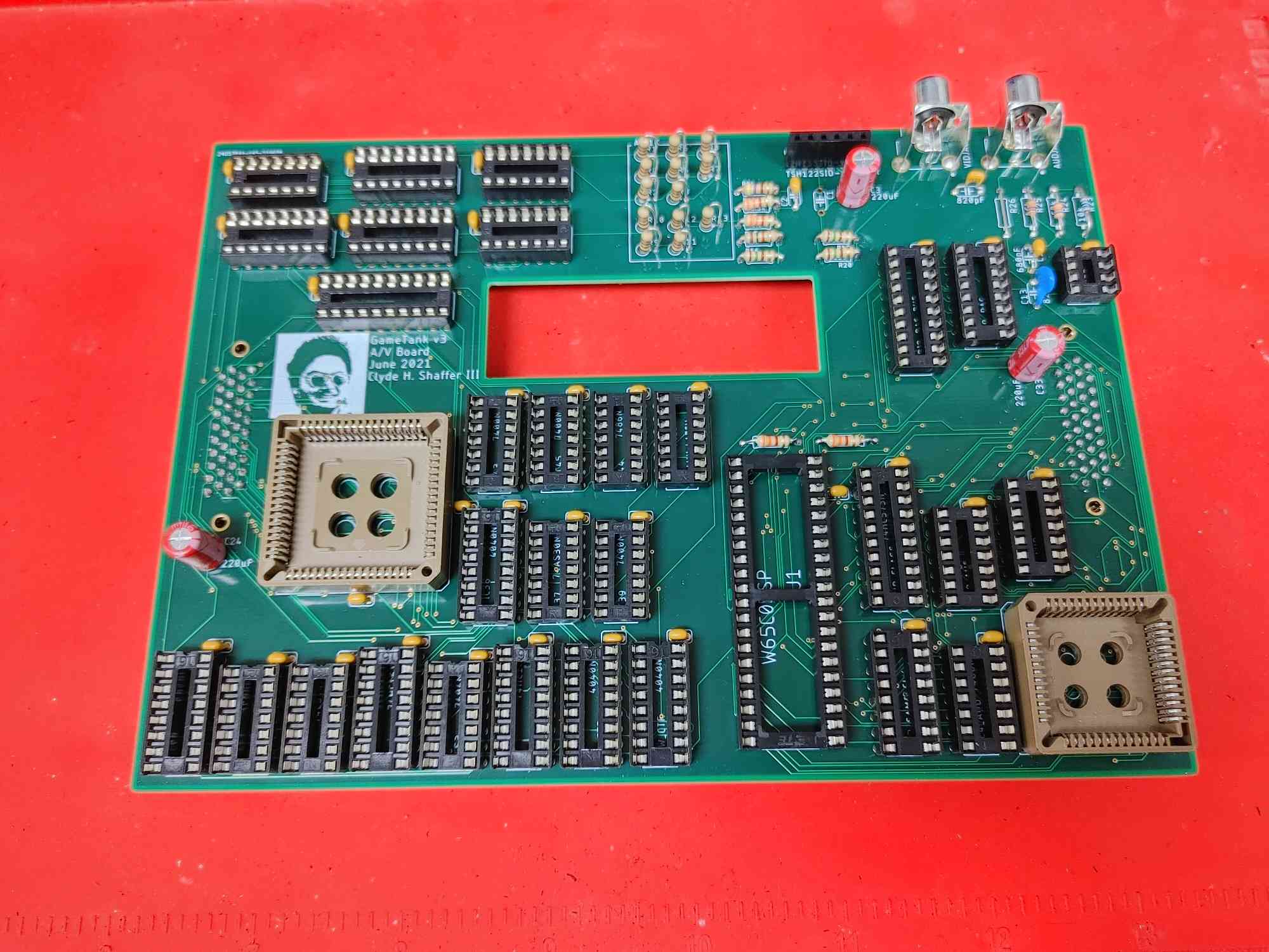
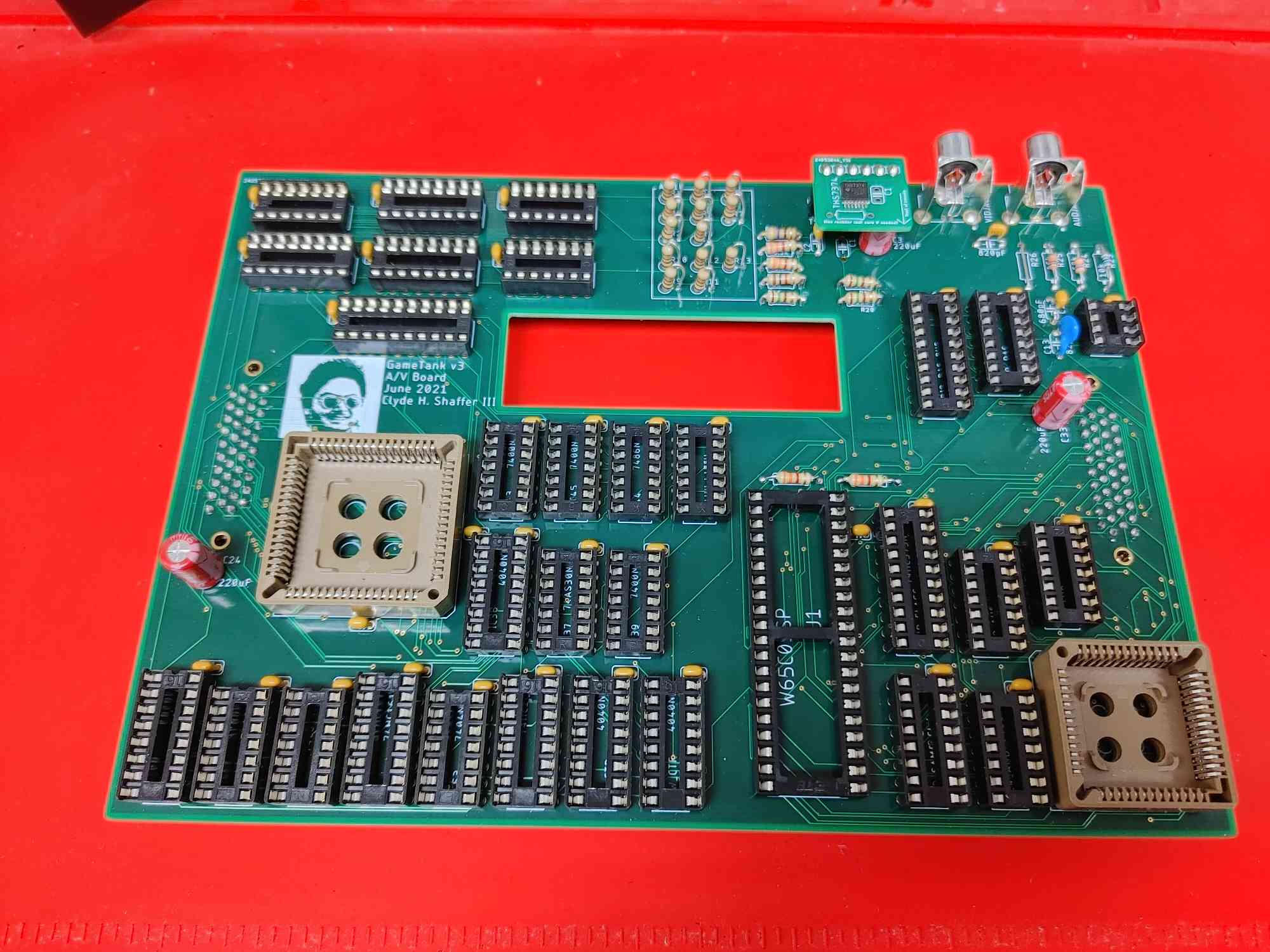
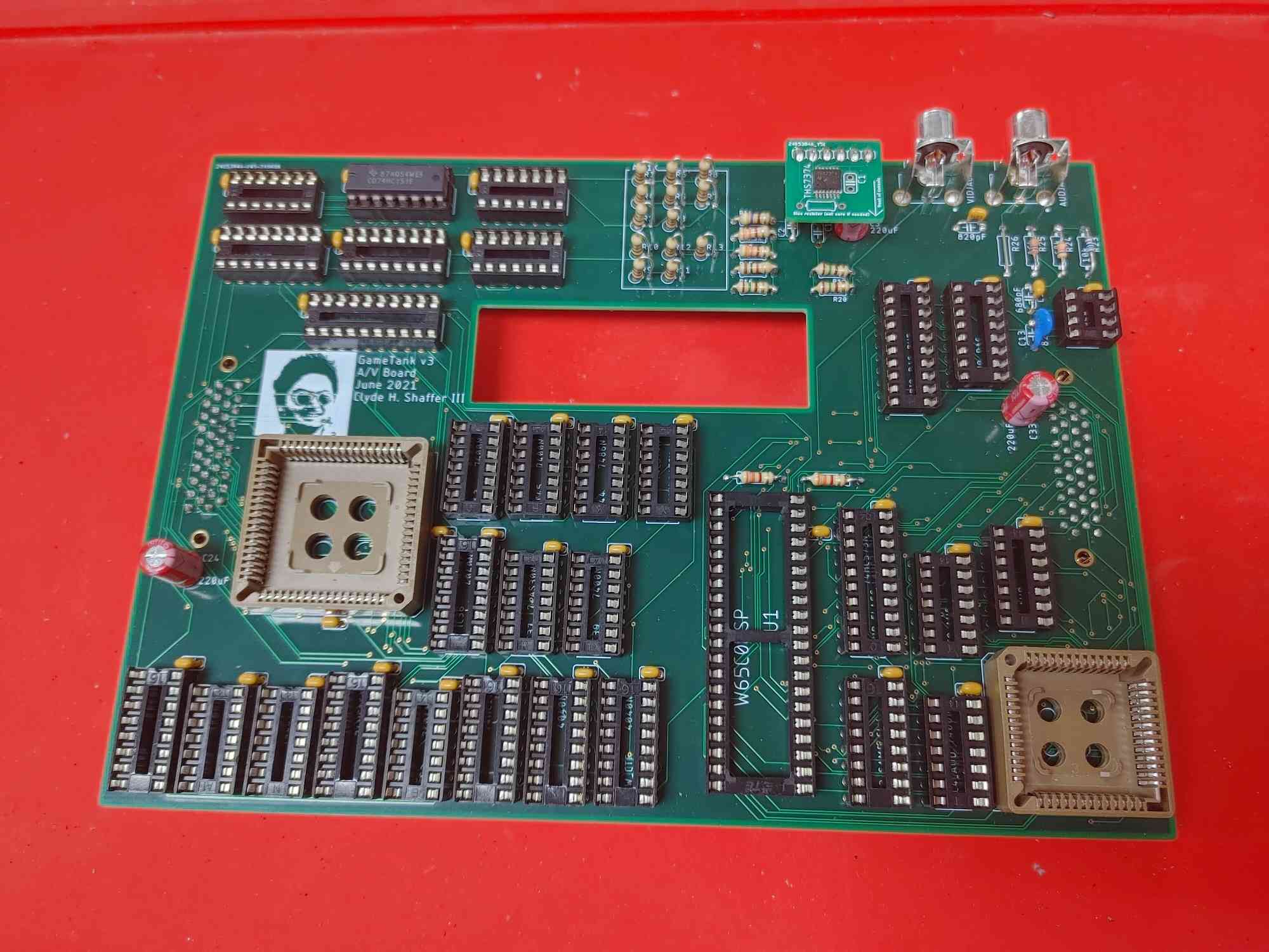
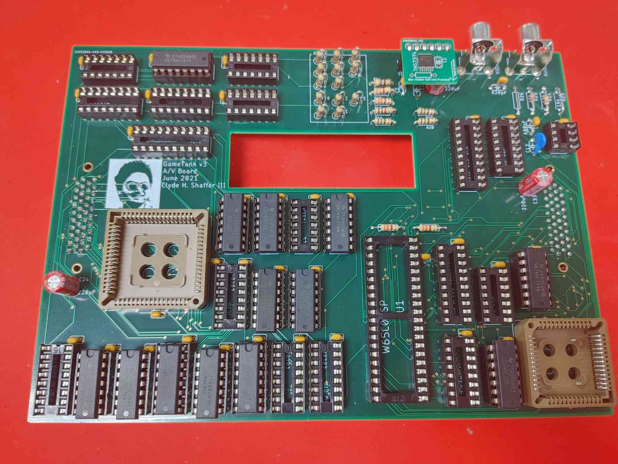
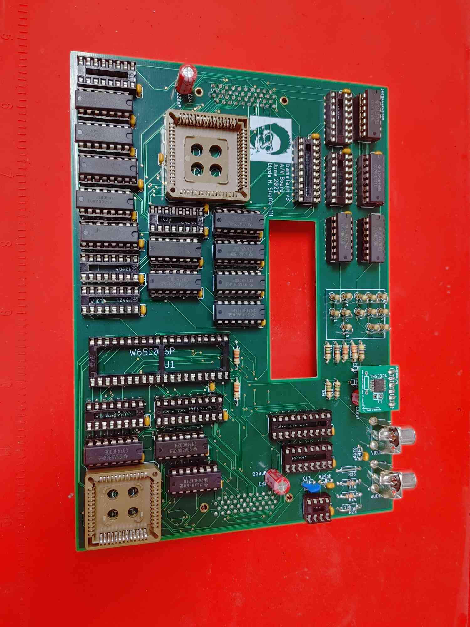
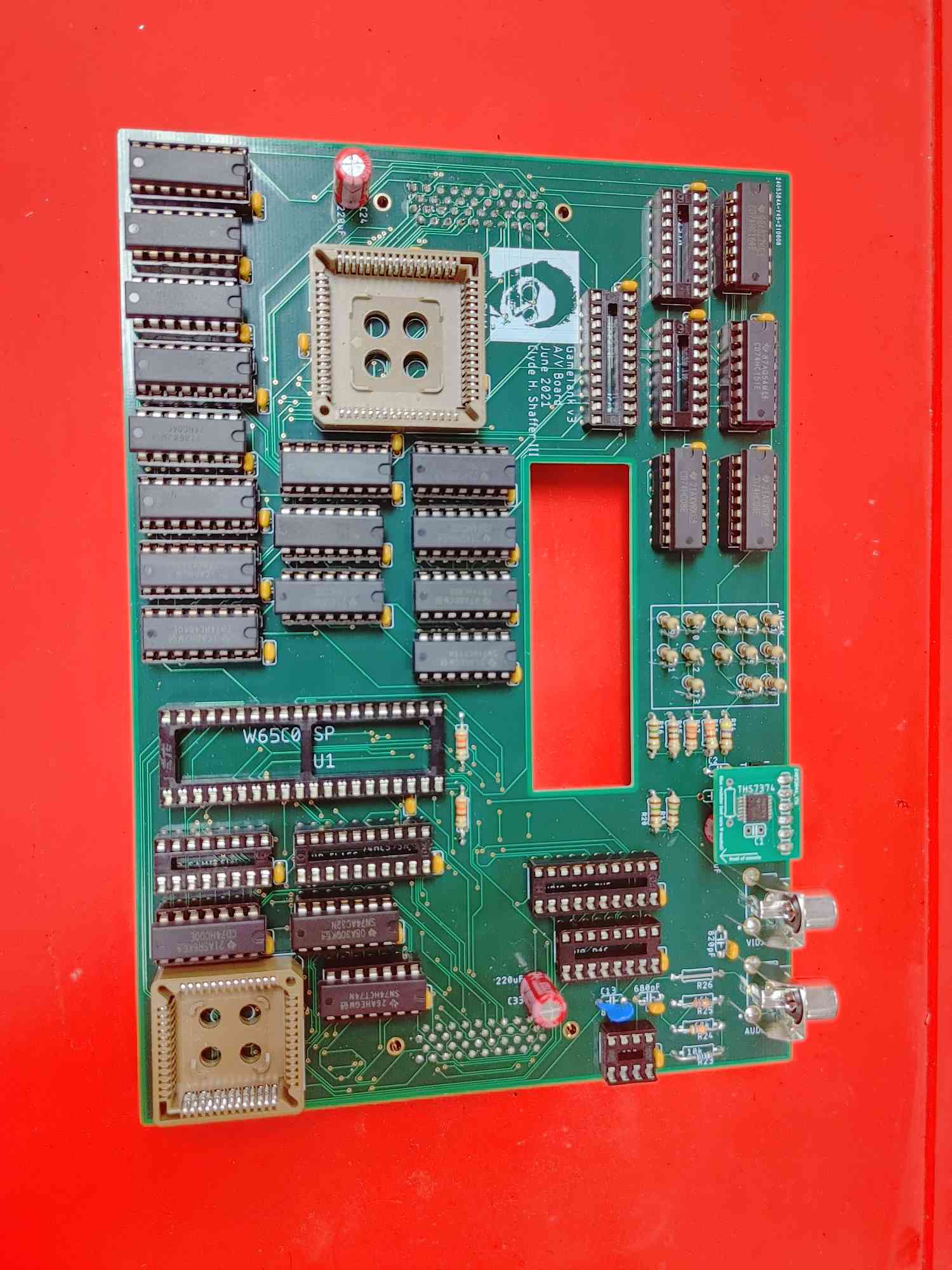
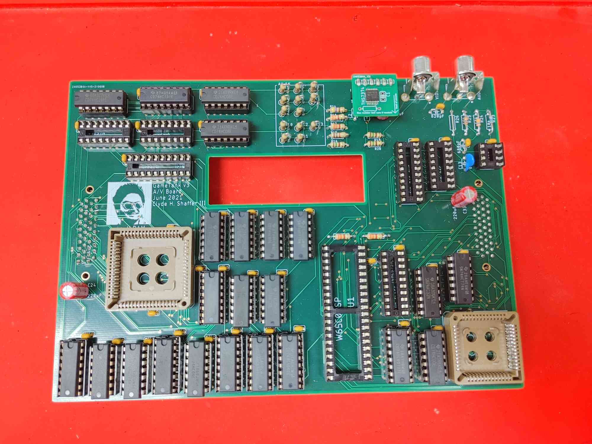
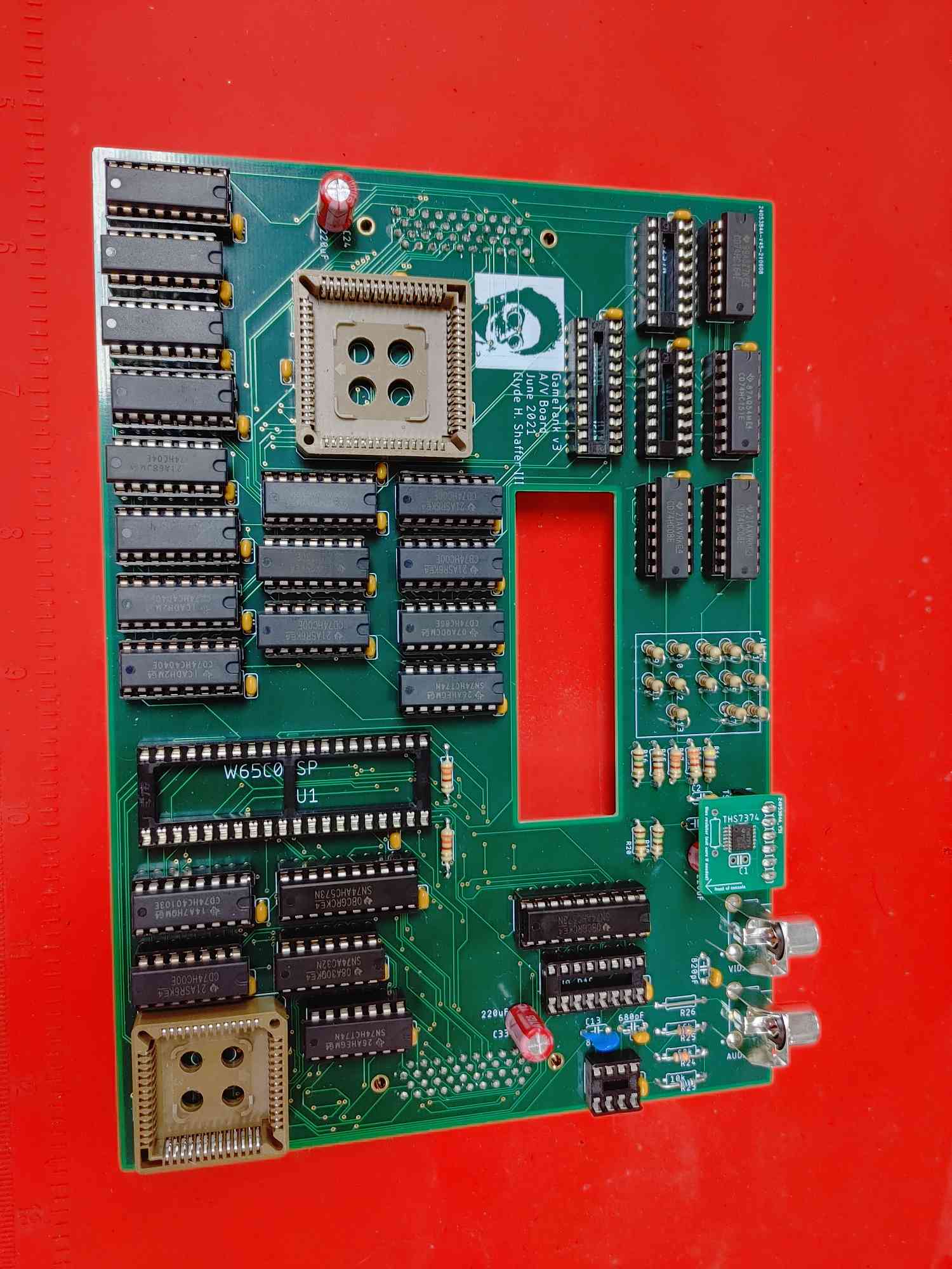
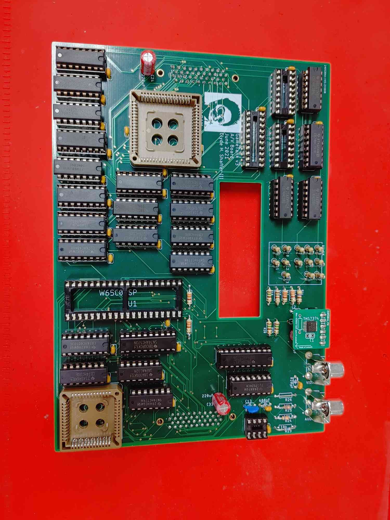
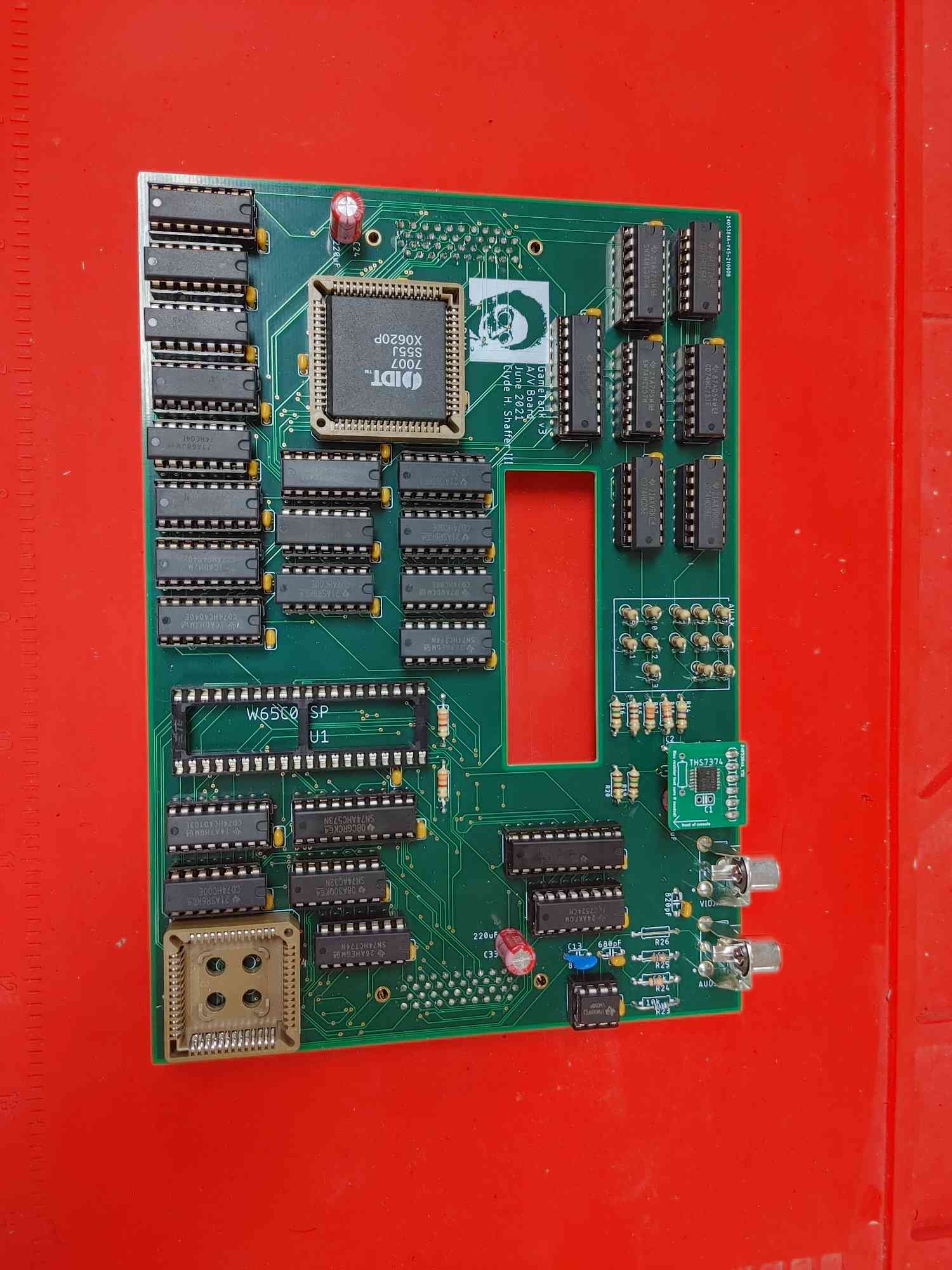
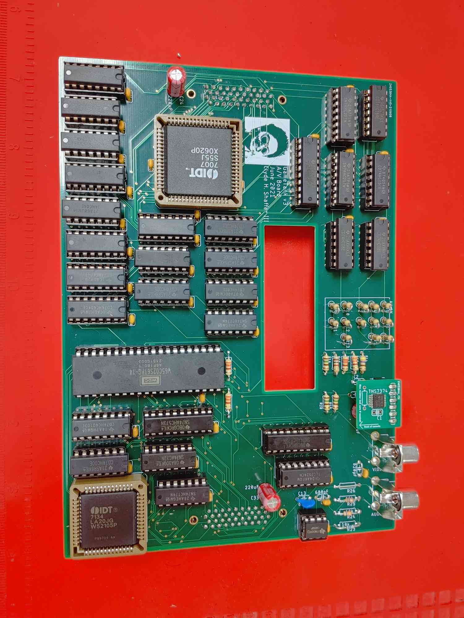
The A/V Board
Photos by @dwbrite
Step 1: Before we begin
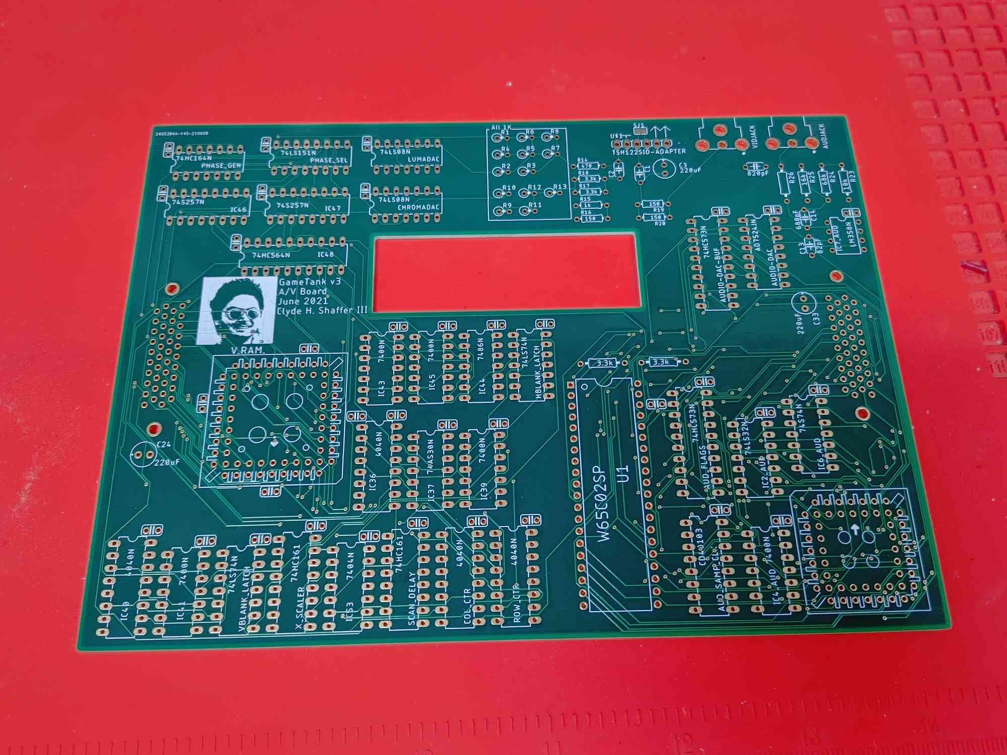
- This page will walk you through building the A/V Board, which generates the signals that go out to the TV.
- In general we'll be placing the shorter components first.
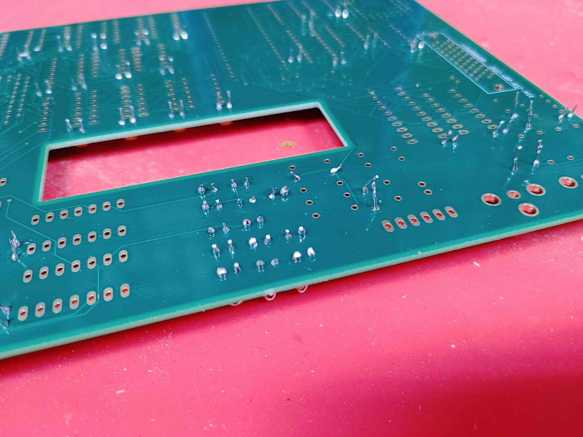
- It will help to have a flat board handy, about the same size as the PCB. This can be used to keep parts from falling out as you flip the whole board to solder components.
Step 2: Bypass Capacitors
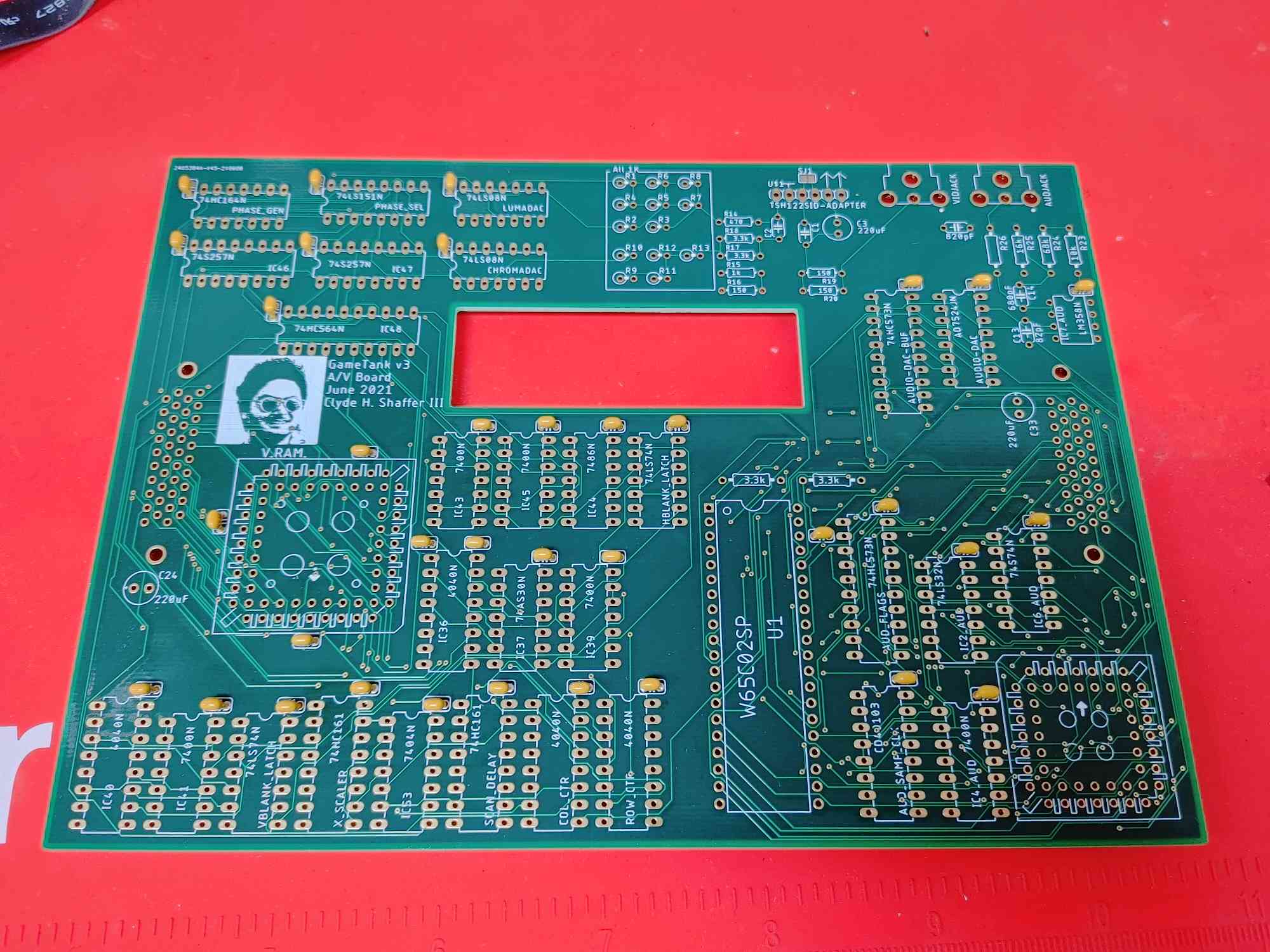
- The bypass capacitors smooth out the power supply to each chip.
- Every IC gets a 0.1uF capacitor next to it.
- There should be 35 of these
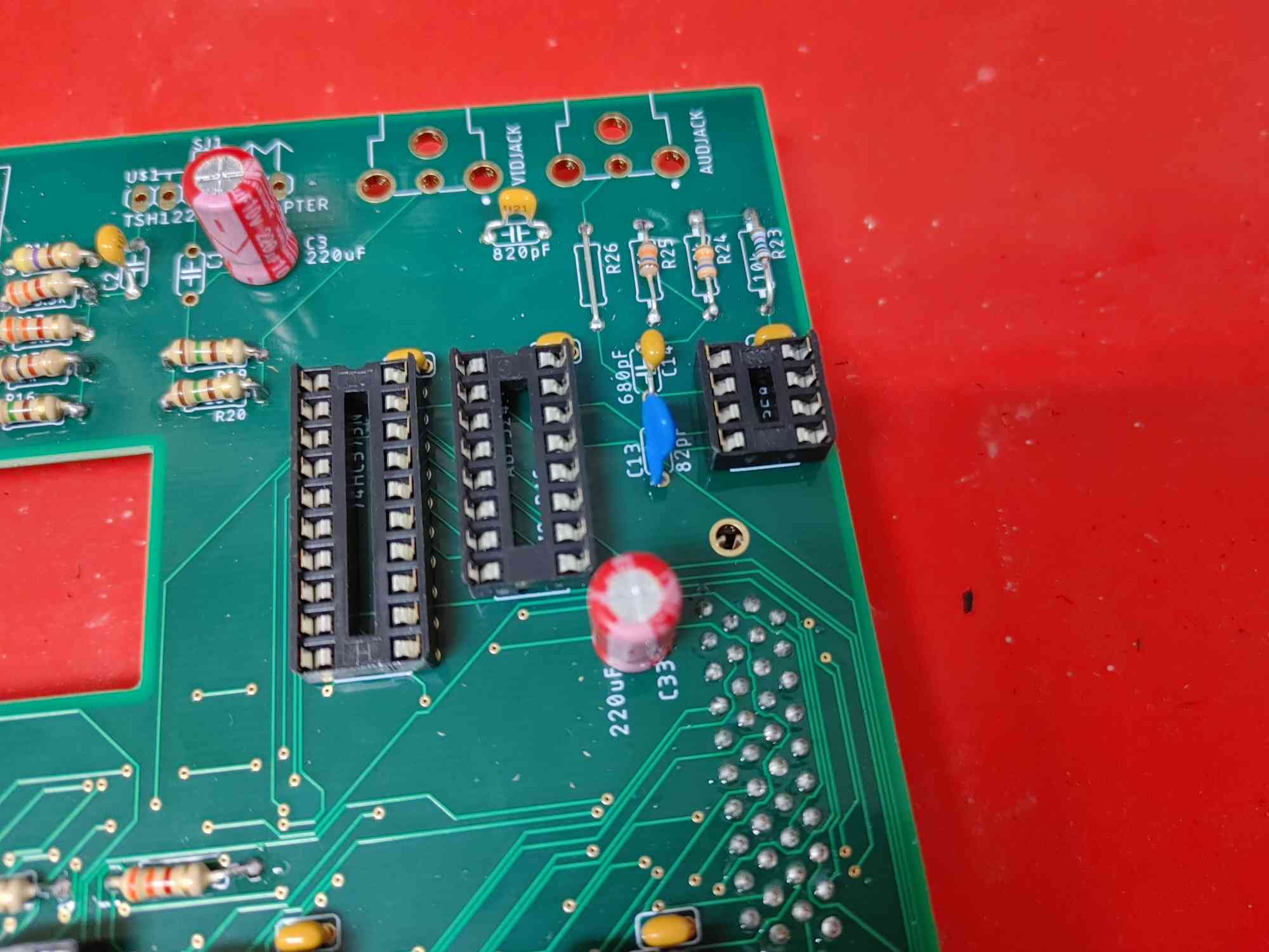
Step 3: Filter Capacitors
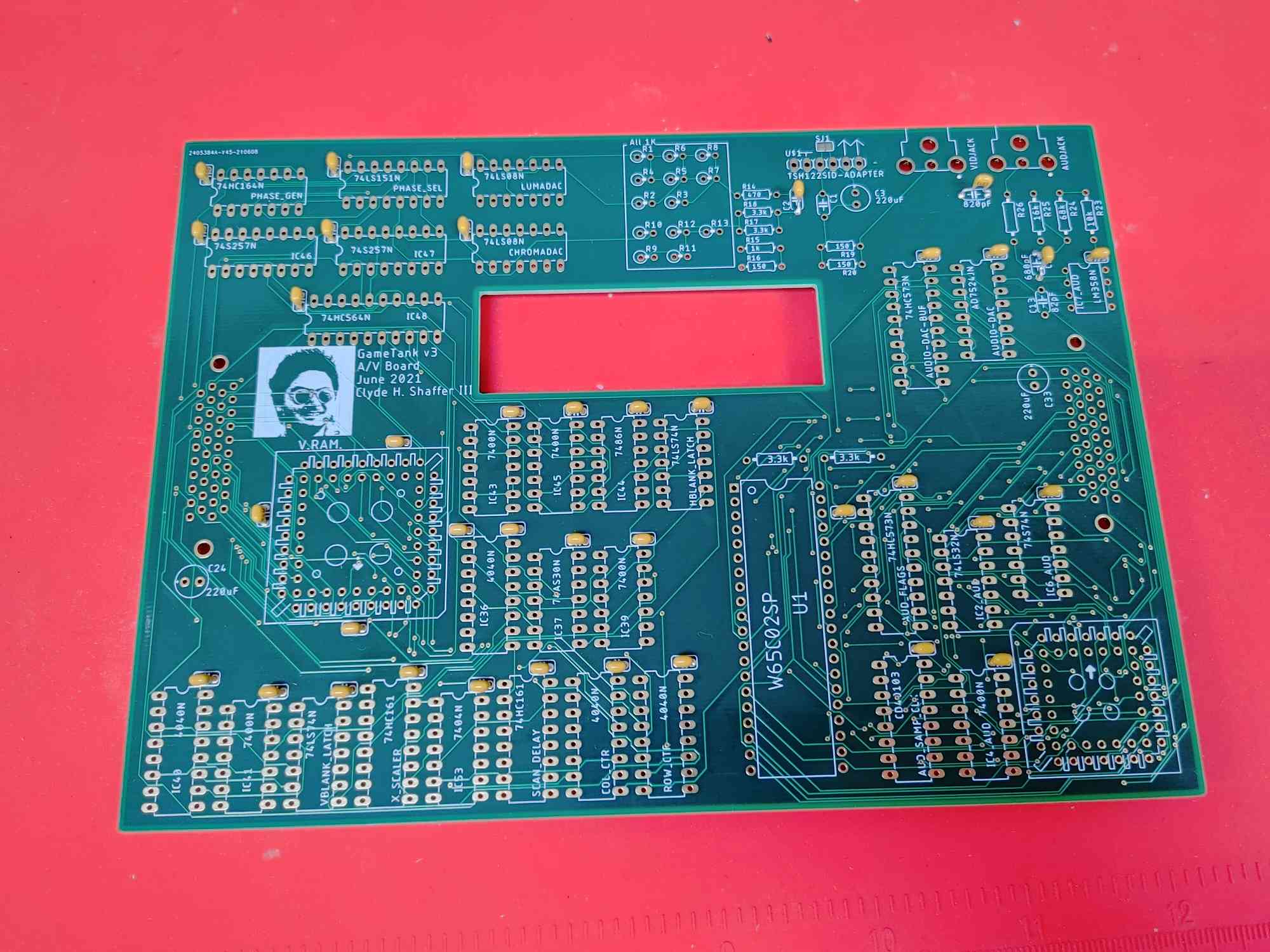
- A few more capacitors are used for audio and video filtering
- Leave C1 vacant
- Use 100pF in C2
- Place the respective capacitors on the slots labeled 680pF, 820pF, and 82pF
- (82pF is missing from the photo due to a shipping error, and will appear in later step photos)
Step 4: 1K Resistors
- There are 14 1kOhm resistors to install
- The resistors inside the rectangle are meant to be installed vertically, as in the picture.
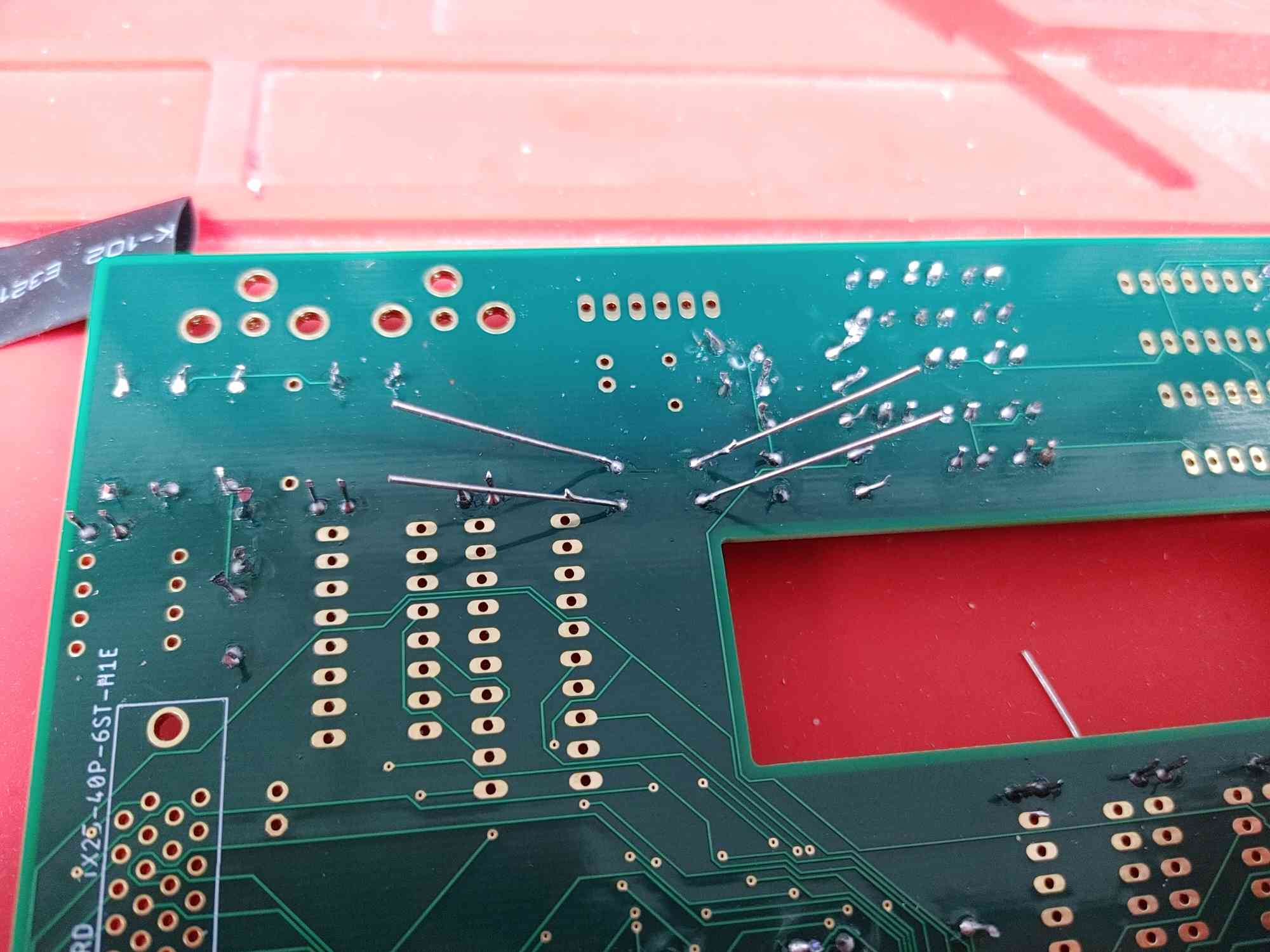
- Cut the resistor leads after soldering
- Bending the legs of horizontal resistors inward can help them stay in place for soldering.
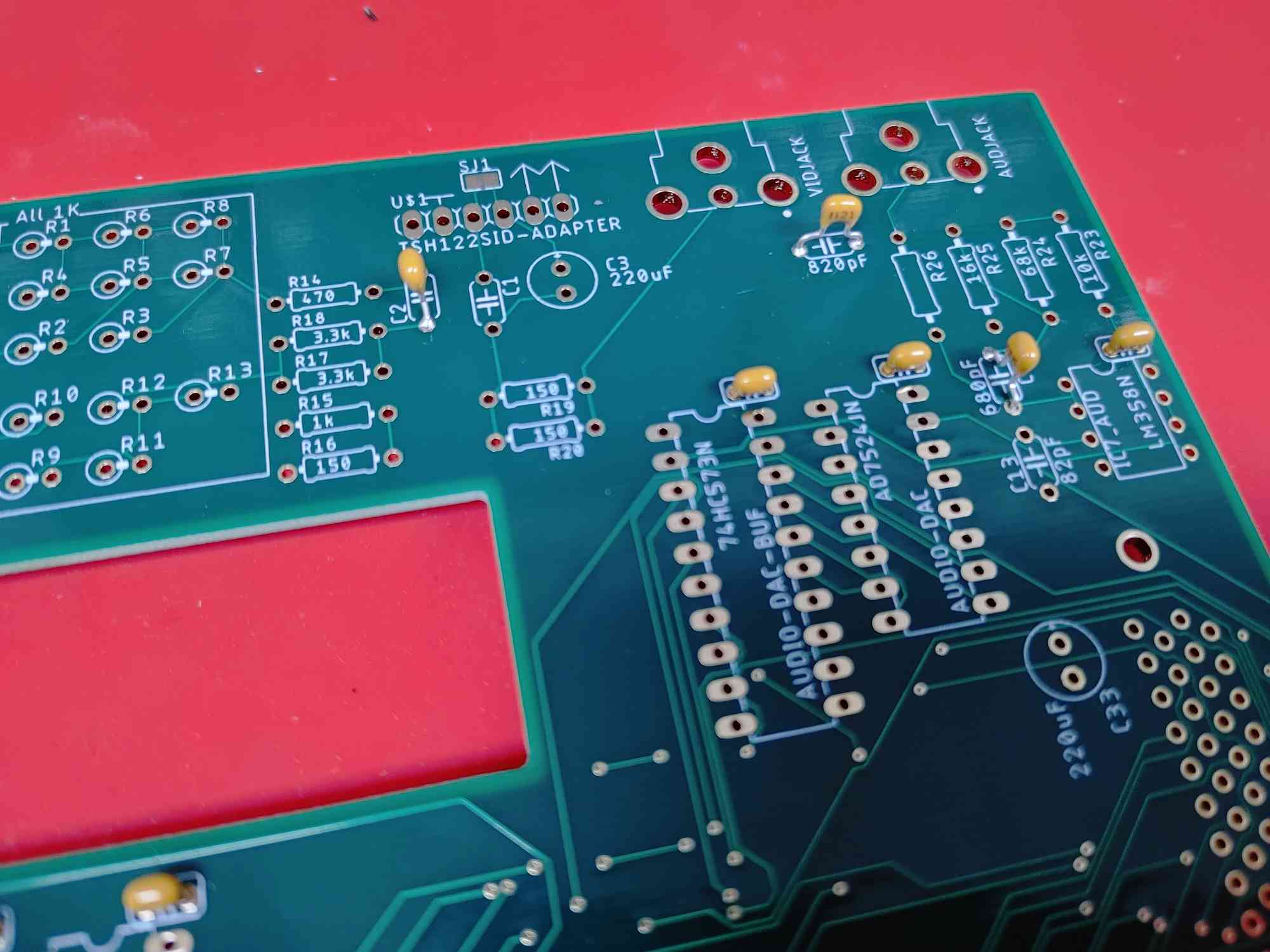
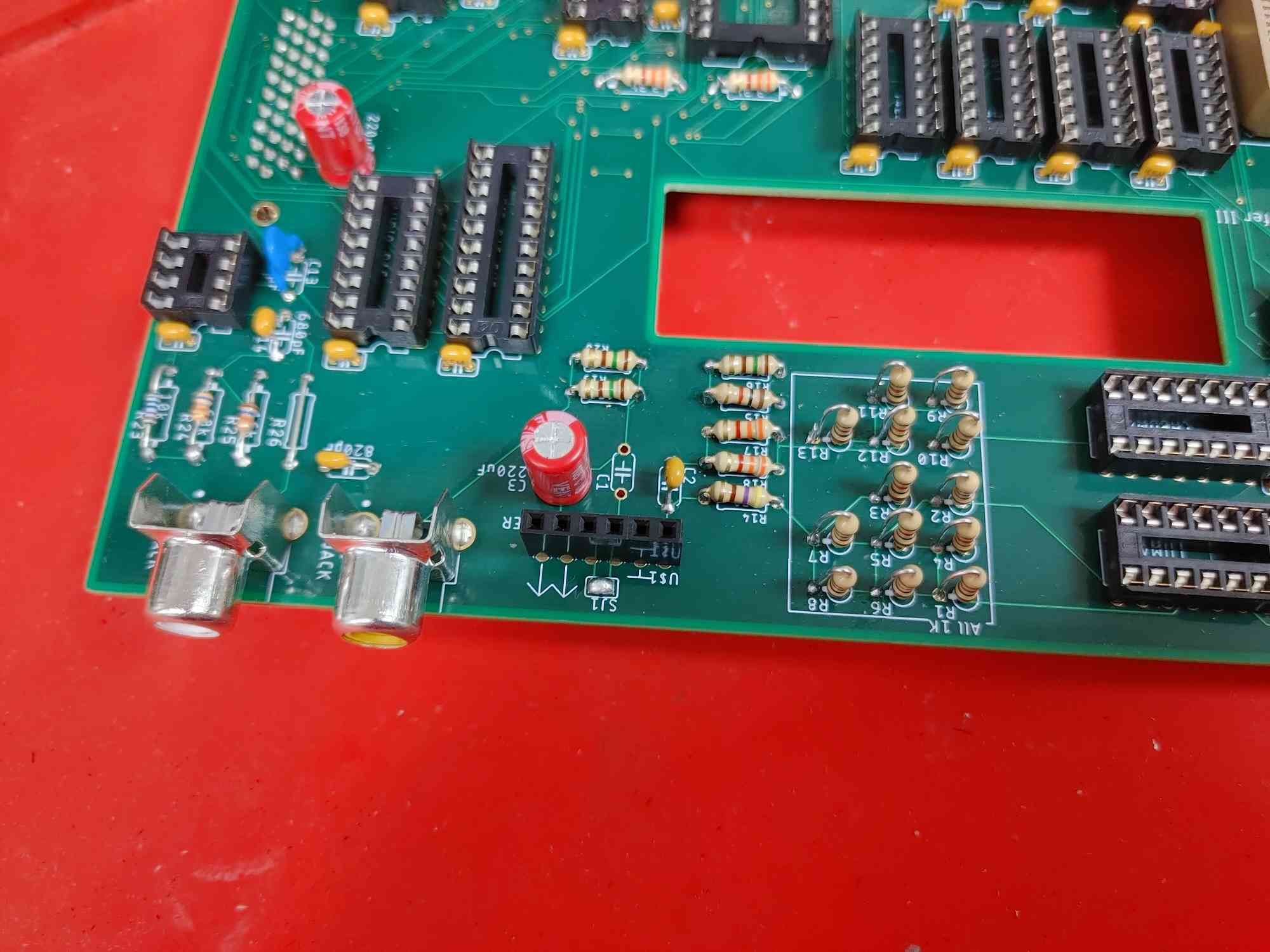
Step 5: Other Resistors
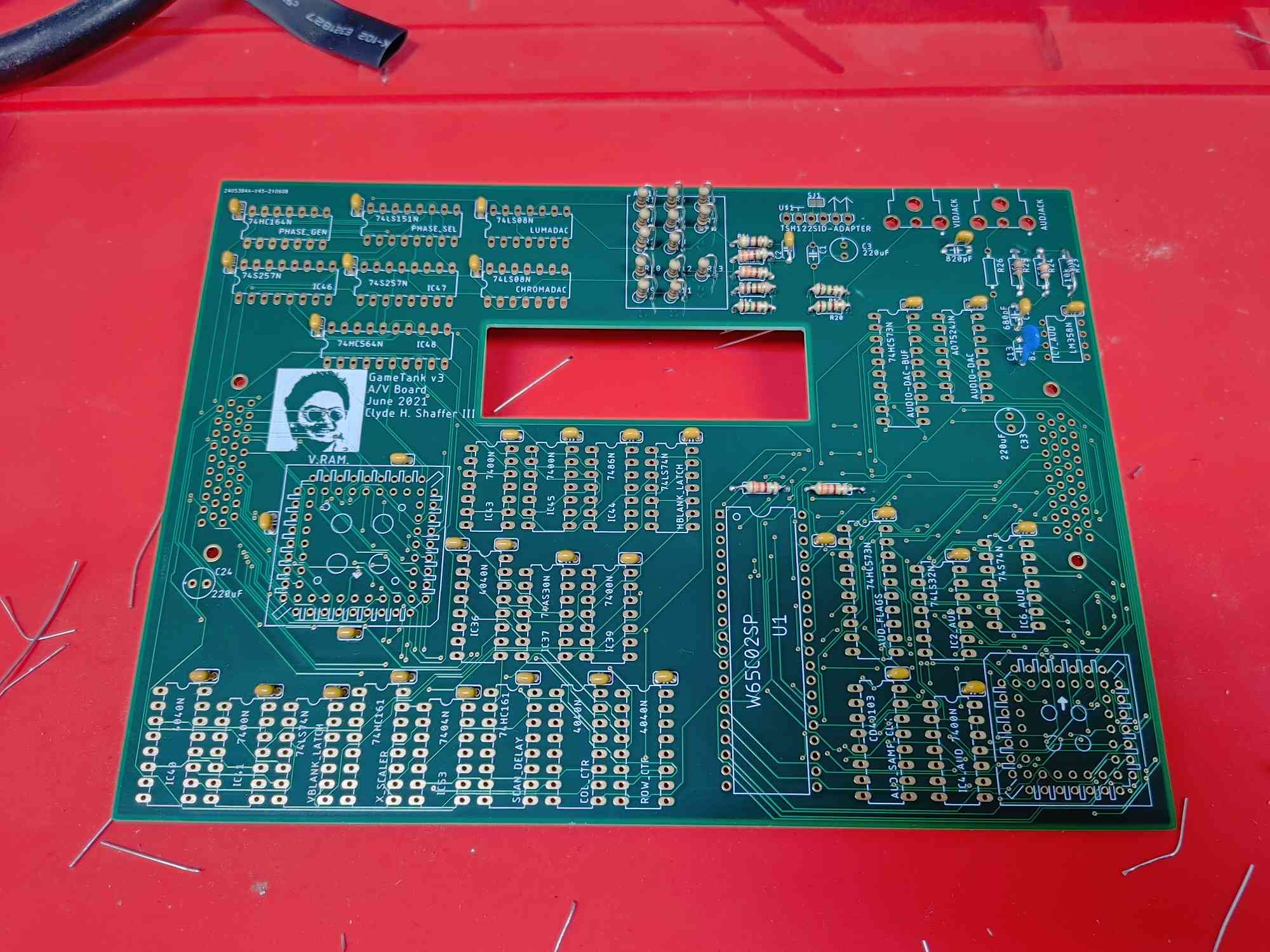
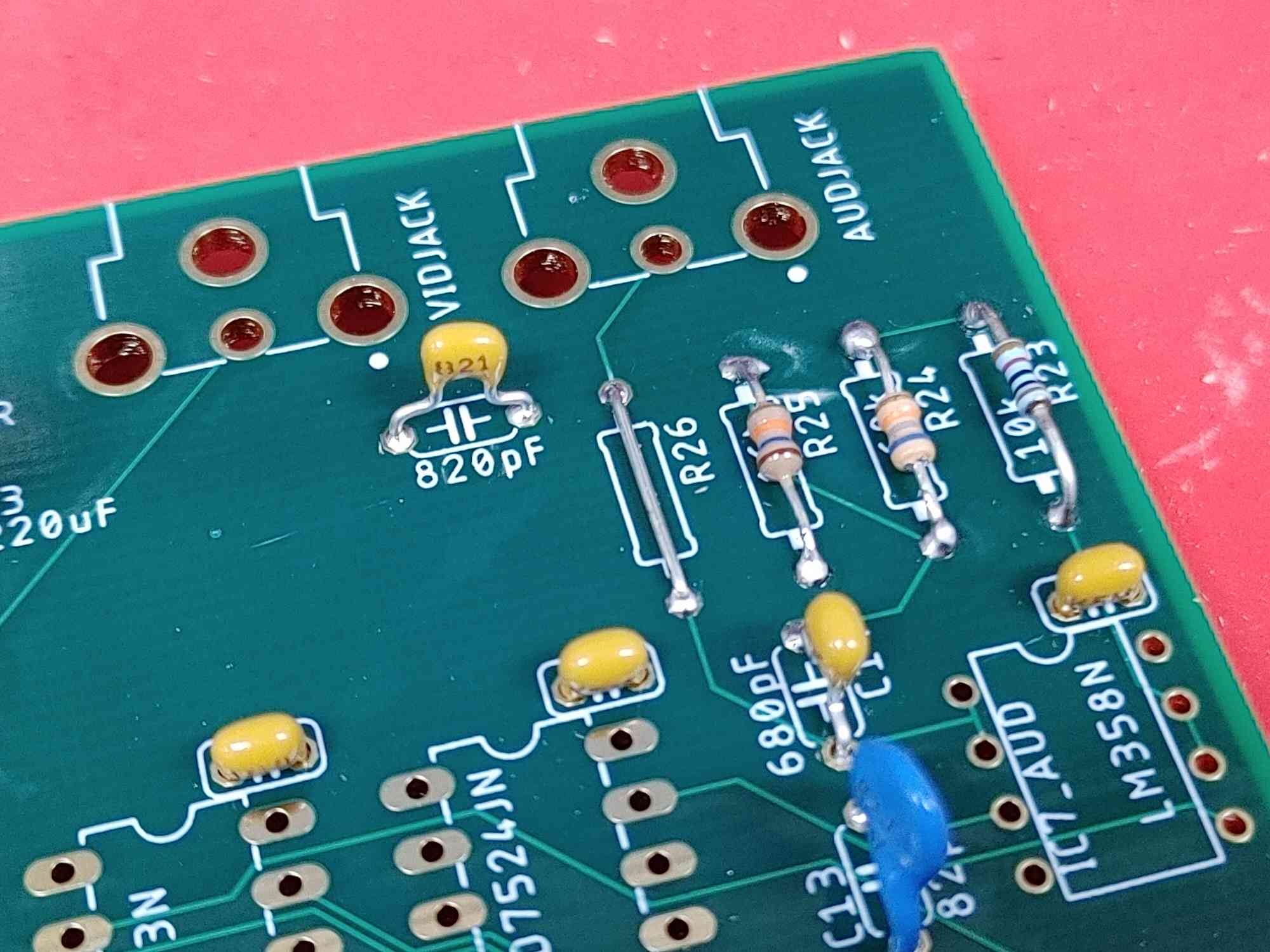
- Install the rest of the resistors according to their labeled value.
- 3 x 150 Ohms
- 4 x 3.3kOhm resistors
- One each of 470, 16k, 68k, 10k
- R26 can be just a wire, such as one clipped from another resistor after soldering.
Step 6: Big Capacitors
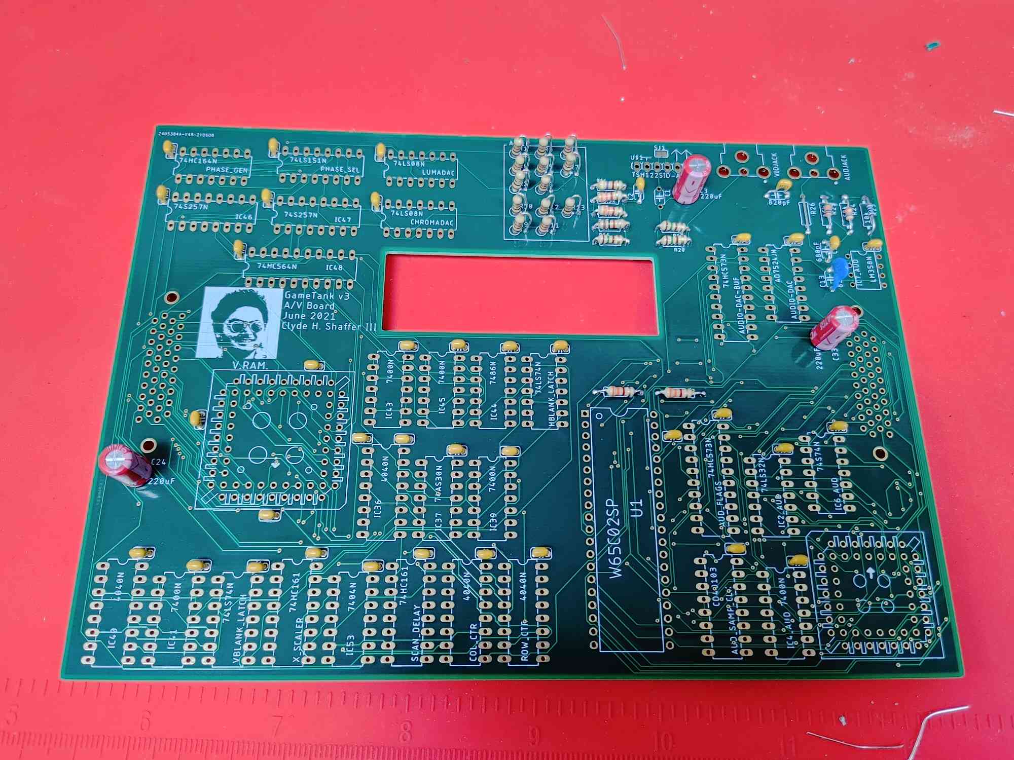
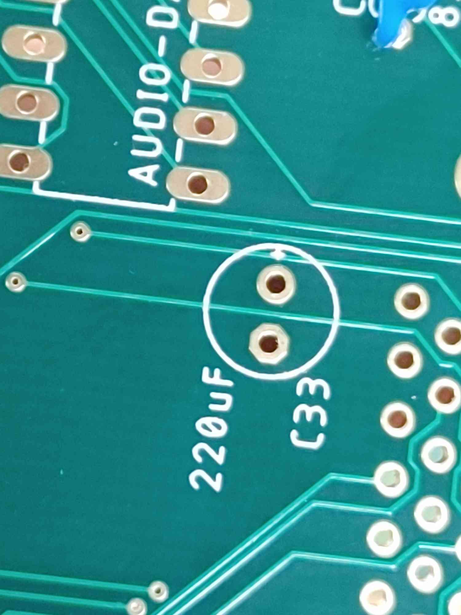
- One filter capacitor for video and the two bypass capacitors for inter-board connectors are big 220uF electrolytic caps
- The symbol for these capacitors has a small "+" plus sign indicating the positive lead
- The capacitor has a stripe indicating the negative lead, which should go in the opposite hole of the plus sign.
Step 7: DIP Sockets (Prelude)
- The next several steps will insert sockets for chips.
- The "wood board" method will still help if the sockets are still the tallest thing on the board.
- Otherwise, you can bend the socket pins outward to help them stay in the holes before soldering.
- BE SURE TO match the divot on the socket to the divot on the printed socket outline!
Step 8: DIP16 Sockets
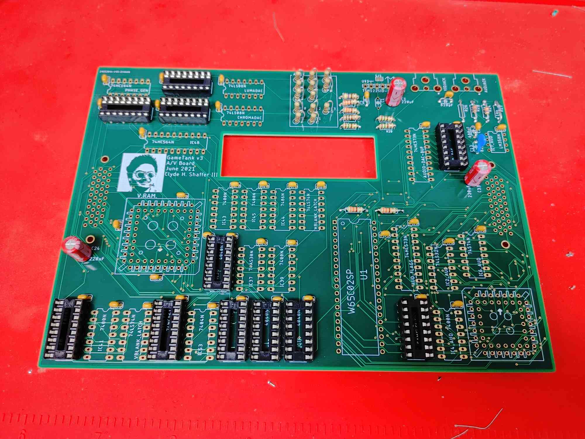
- Next insert the DIP16 sockets, which have two rows of eight pins.
- There should be 11 of these on the A/V board.
Step 9: DIP14 Sockets
- Now insert the DIP14 sockets, which have two rows of seven pins.
- There are places for 15 of these.
Step 10: DIP20 Sockets
- Install the DIP20 sockets, with two rows of ten pins.
- You'll be placing 3 of them.
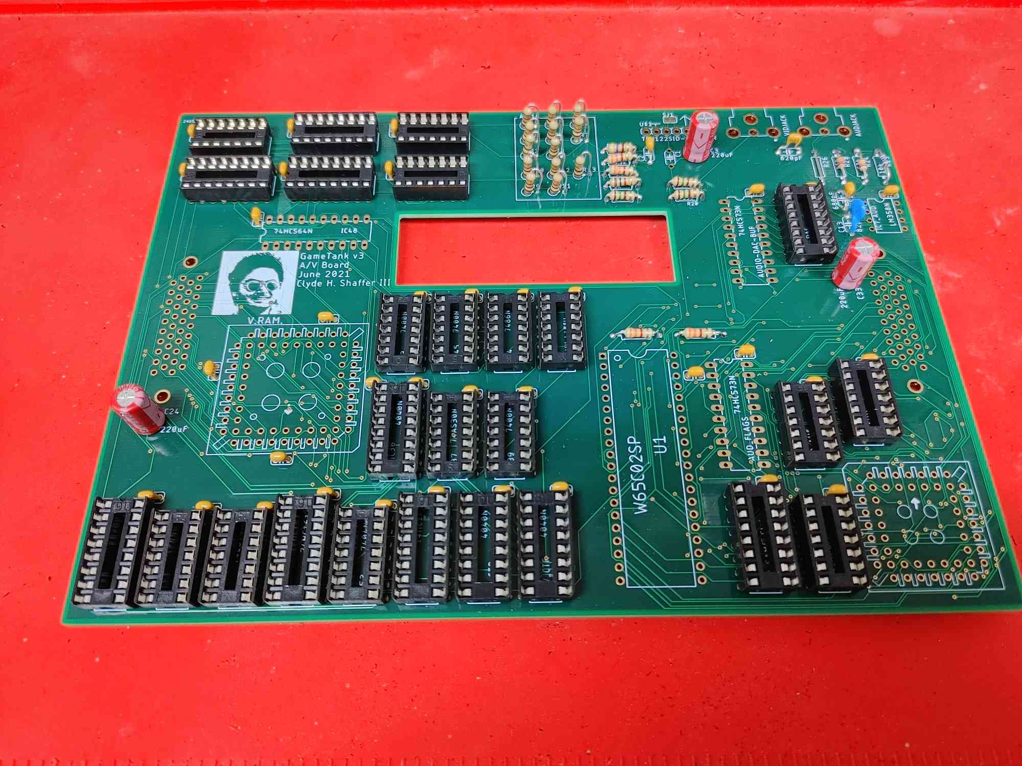
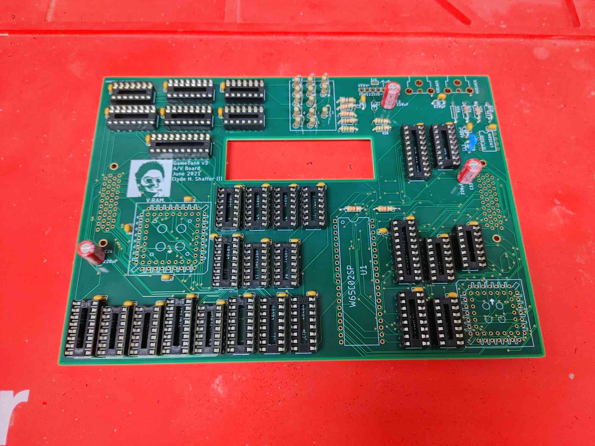
Step 11: DIP40 Socket
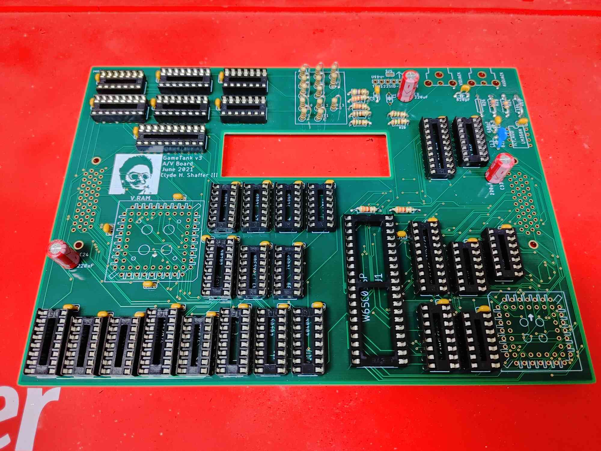
- The next socket is the DIP40 that will hold one of the GameTank's two 6502 CPUs
- There is only one place for a DIP40 socket on the A/V board
- This CPU will be the Audio Coprocessor
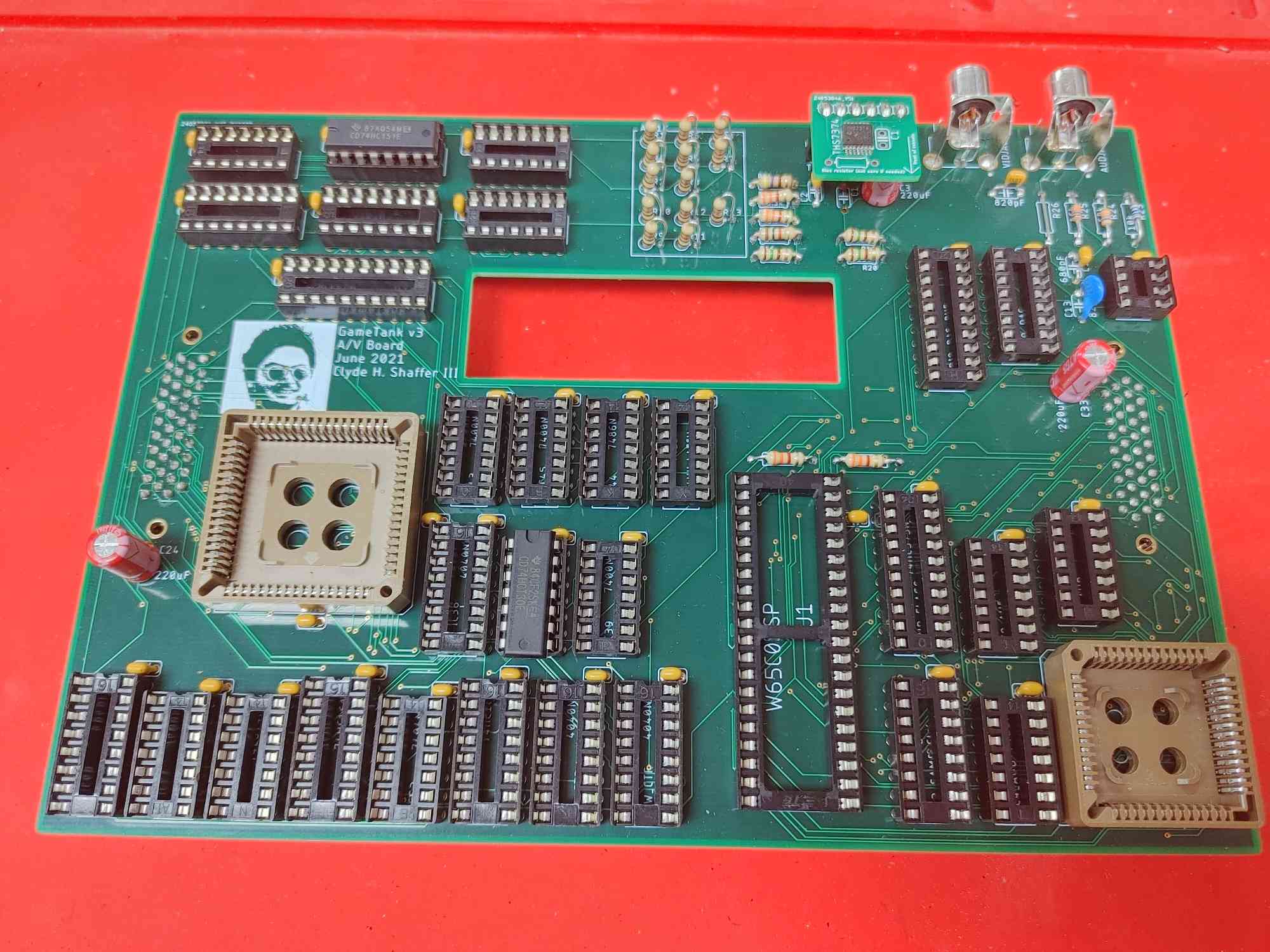
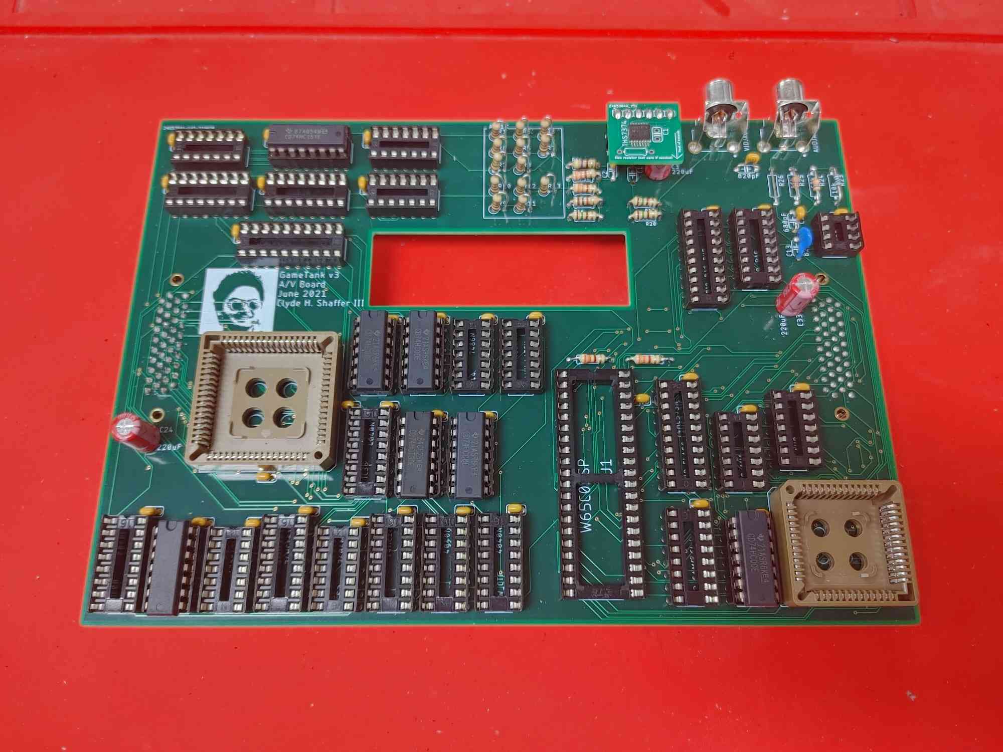
Step 12: PLCC Sockets (The square ones)
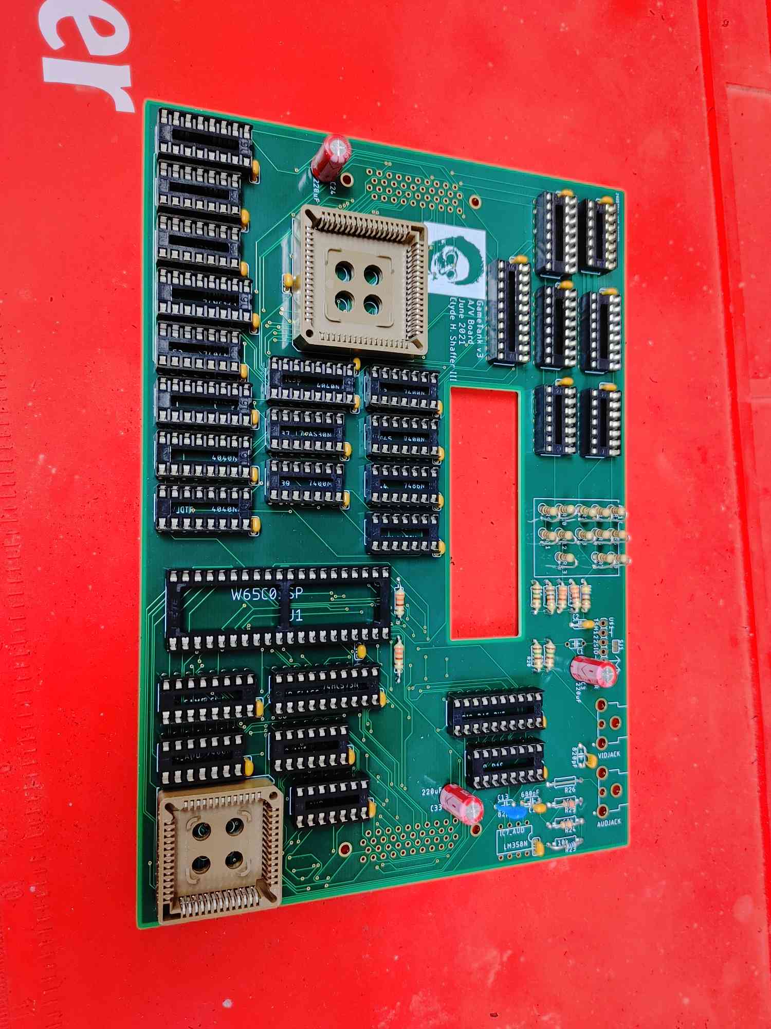
- There are two square sockets to install, which will hold the Video RAM and Audio RAM chips.
- Be sure to match the direction of the arrows on the sockets to the arrows printed on the board.
- "Protip rest it on something and get the corners first." - dwbrite
Step 13: Inter-board connectors
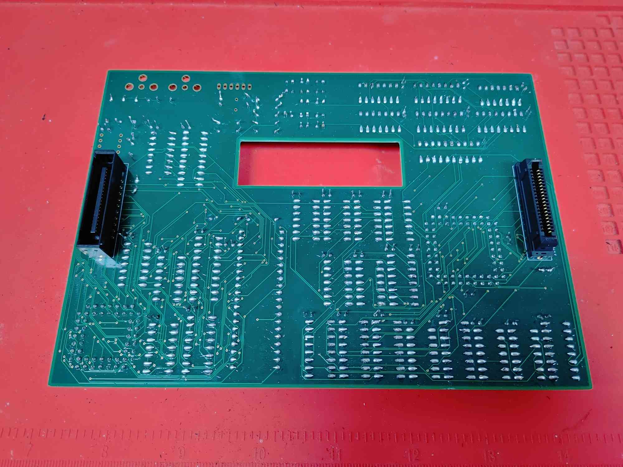
- Next, install the two inter-board connectors on the BOTTOM of the board.
- You'll need one "receptacle" and one "plug" connector
- IMPORTANT: Each of the connectors has a single corner flattened on a diagonal. These diagonals should be oriented INWARD towards the cartridge hole for consistency.
Step 15: A/V Output Jacks
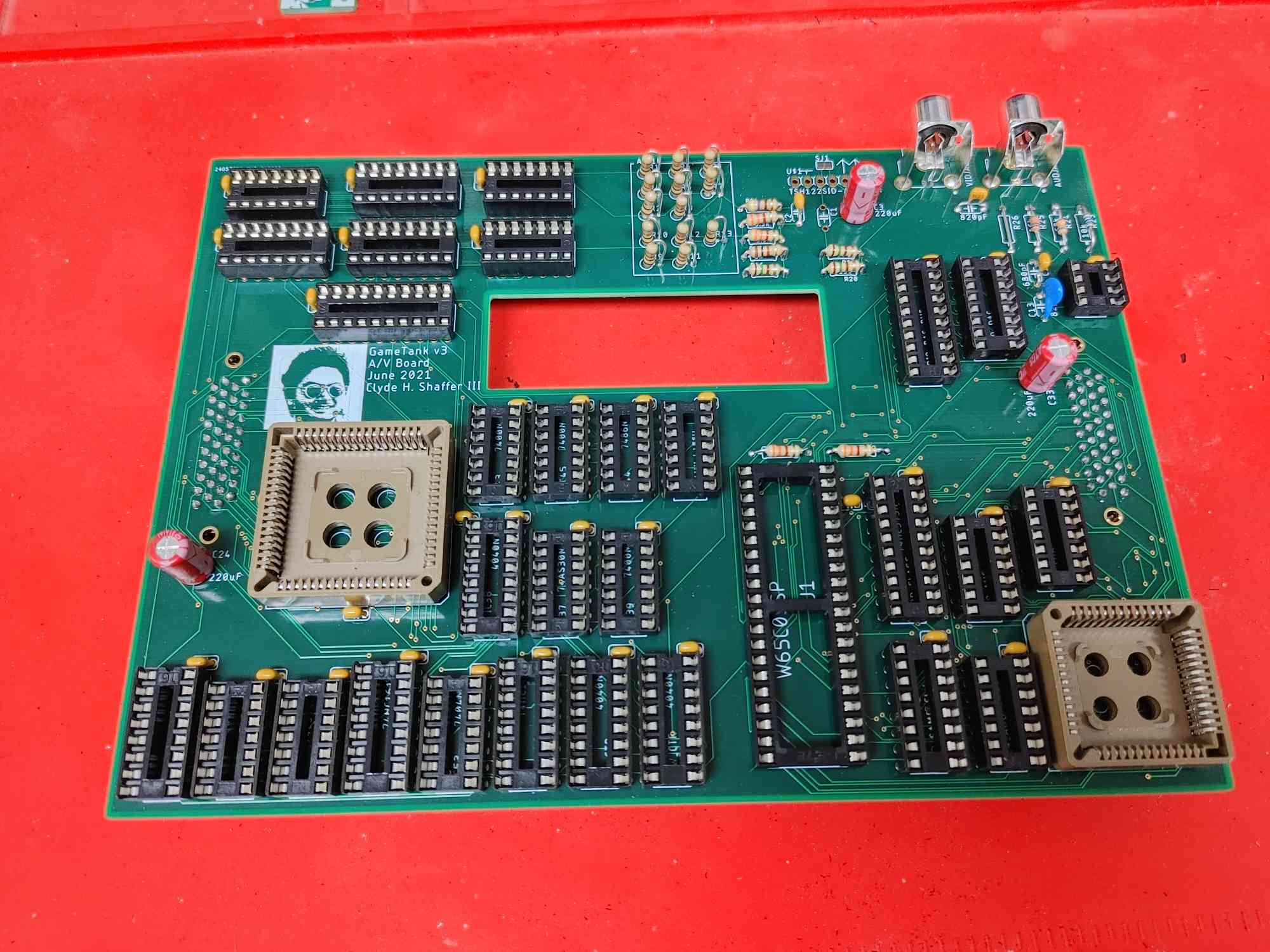
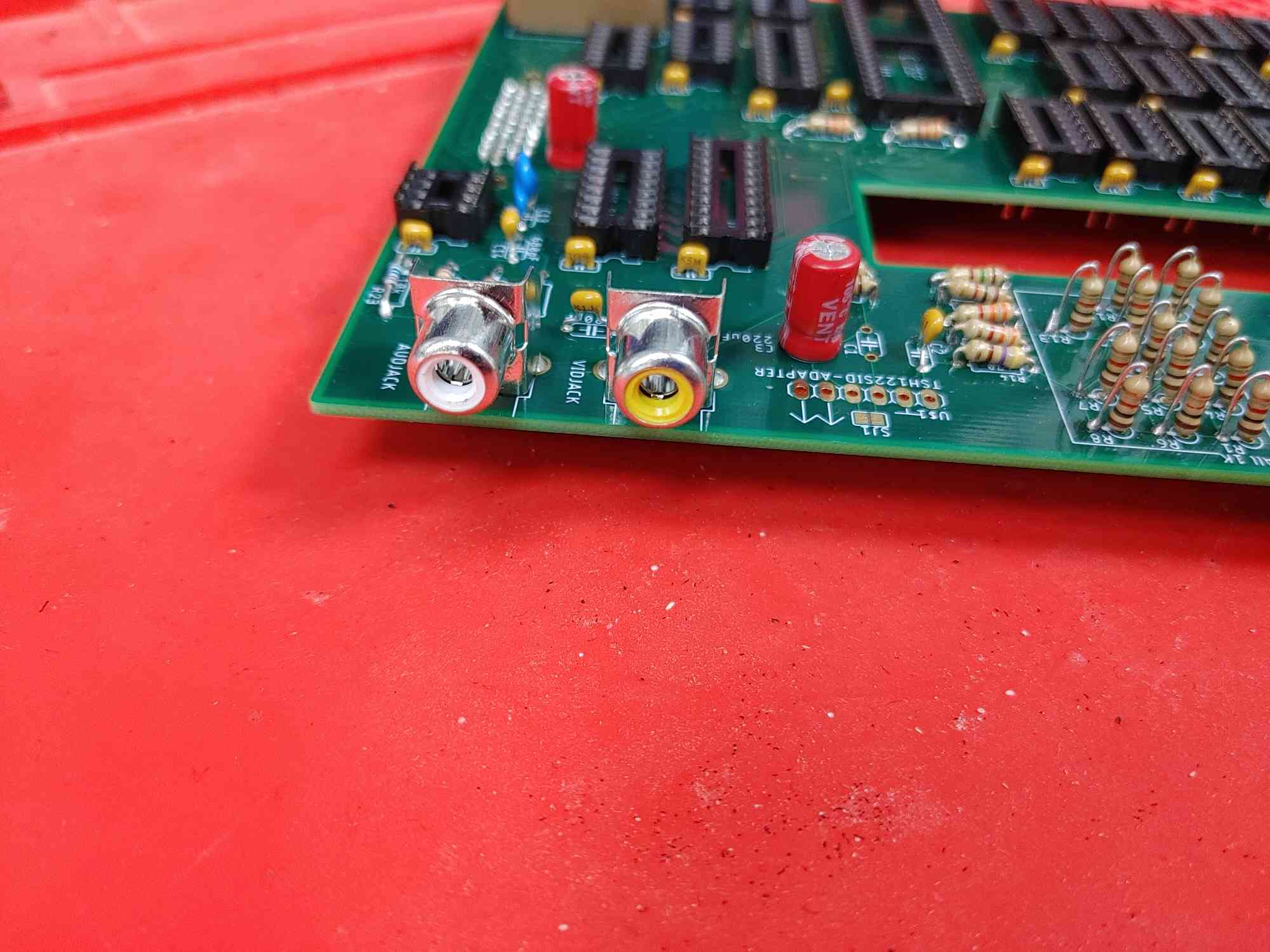
- Install the two RCA-style conectors on the corner of the PCB
- The yellow connector should go on VIDJACK
- The white connector should go on AUDJACK
Step 18: Assemble the Video Buffer Amp
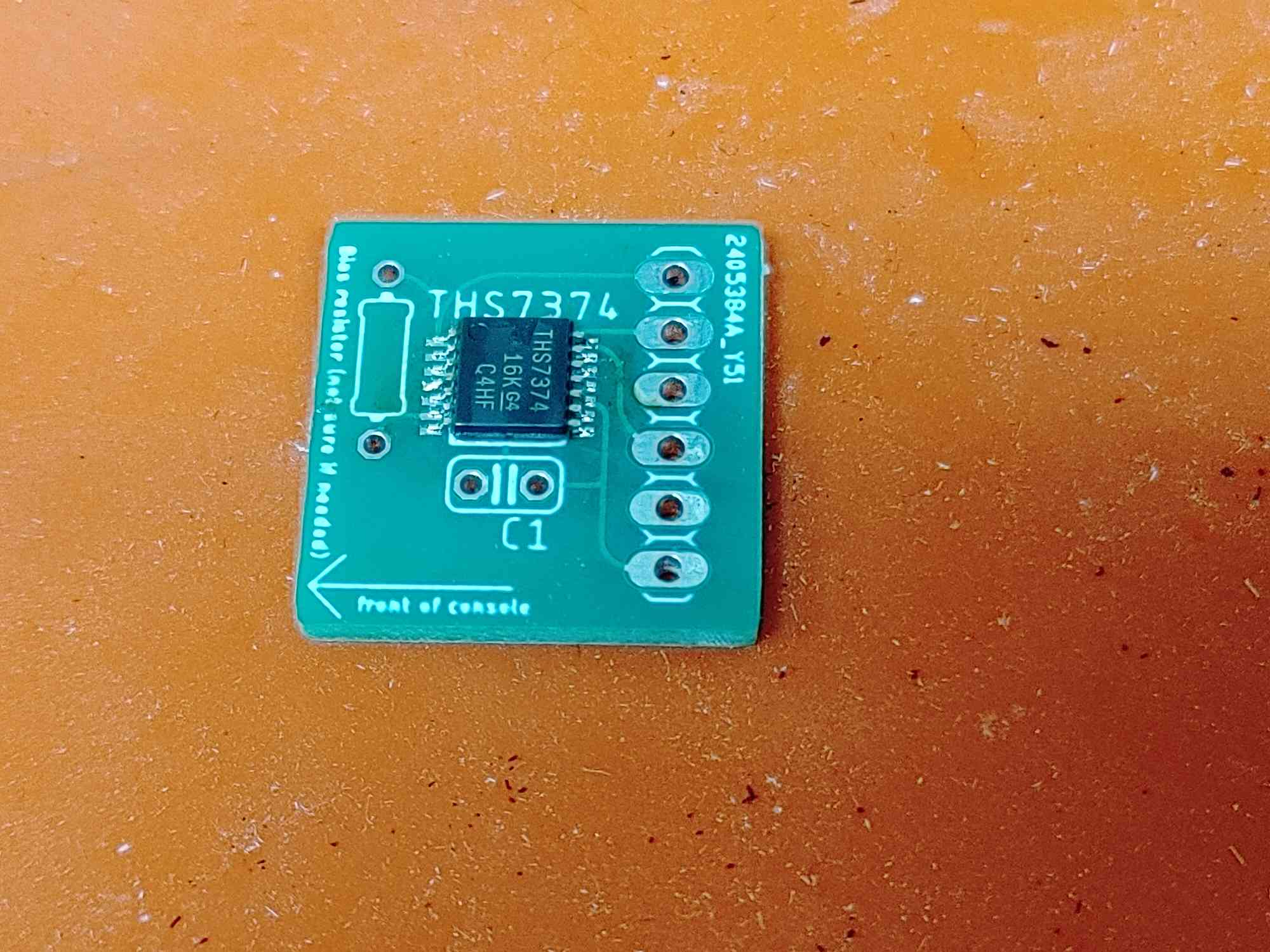
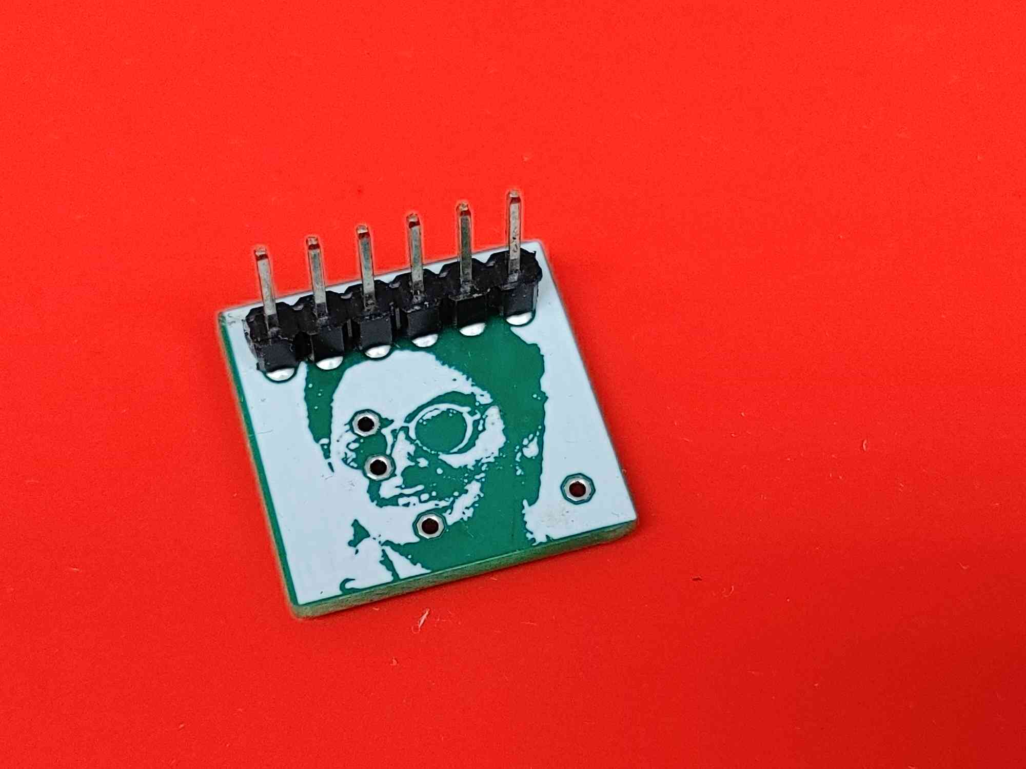
- If you didn't request a pre-soldered module, this will be one of the two surface-mount soldering tasks in the console.
- This will use the small PCB with THS7374 printed on it, as well as the chip with the same name.
- Flux and low-temperature solder paste are recommended
- Align the THS7374 to the outline, matching the divot on the chip to the printed dot on the board.
- This can be soldered with an iron, hot air gun, oven, or hot plate.
- If any pins are bridged, add flux and use copper braid to remove excess solder.
- C1 and the resistor outline on this module can be left vacant with no issues.
- Then solder on the 6-pin male header to the BOTTOM of the board.
Step 19: Install the Video Buffer Amp
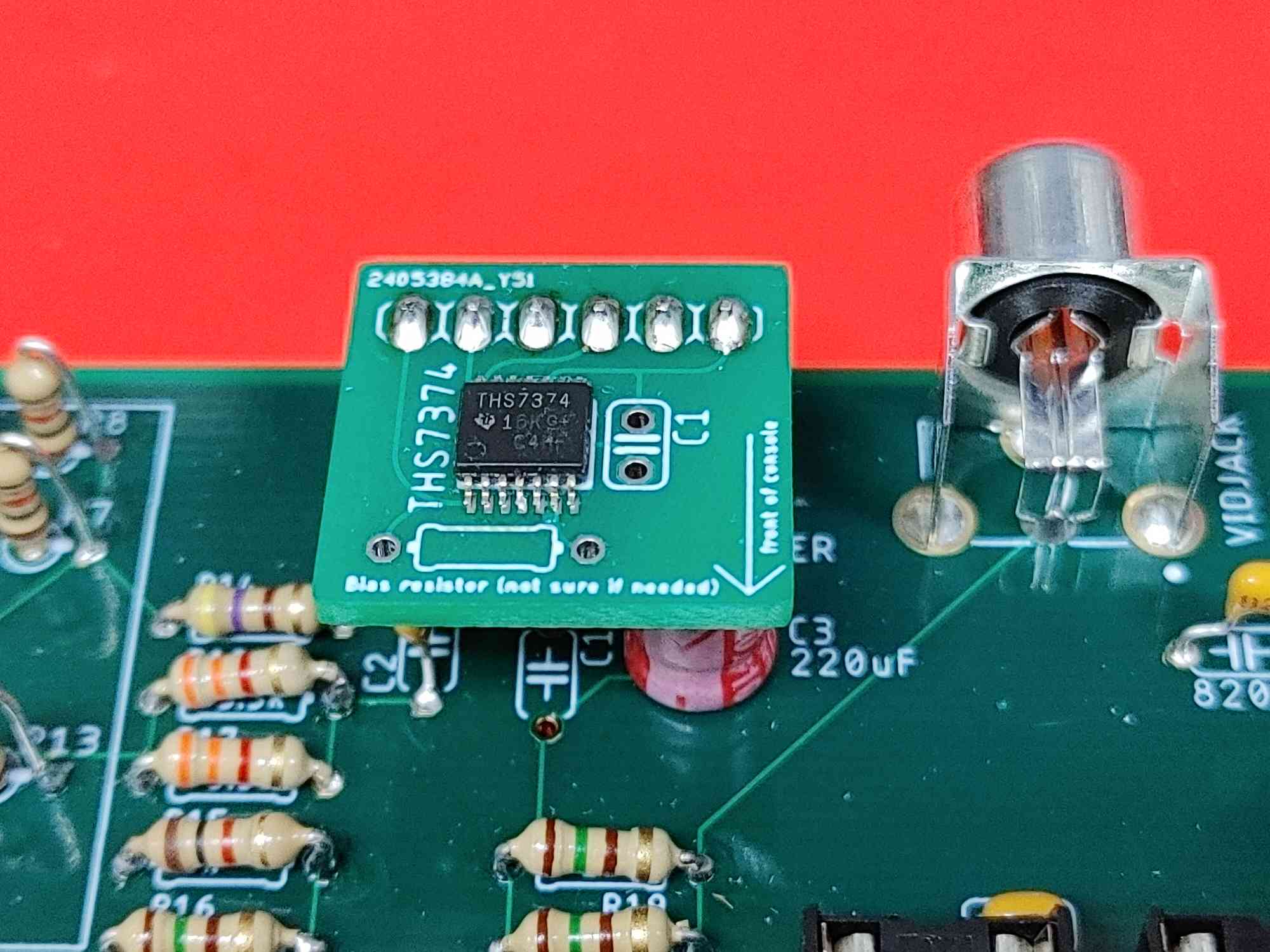
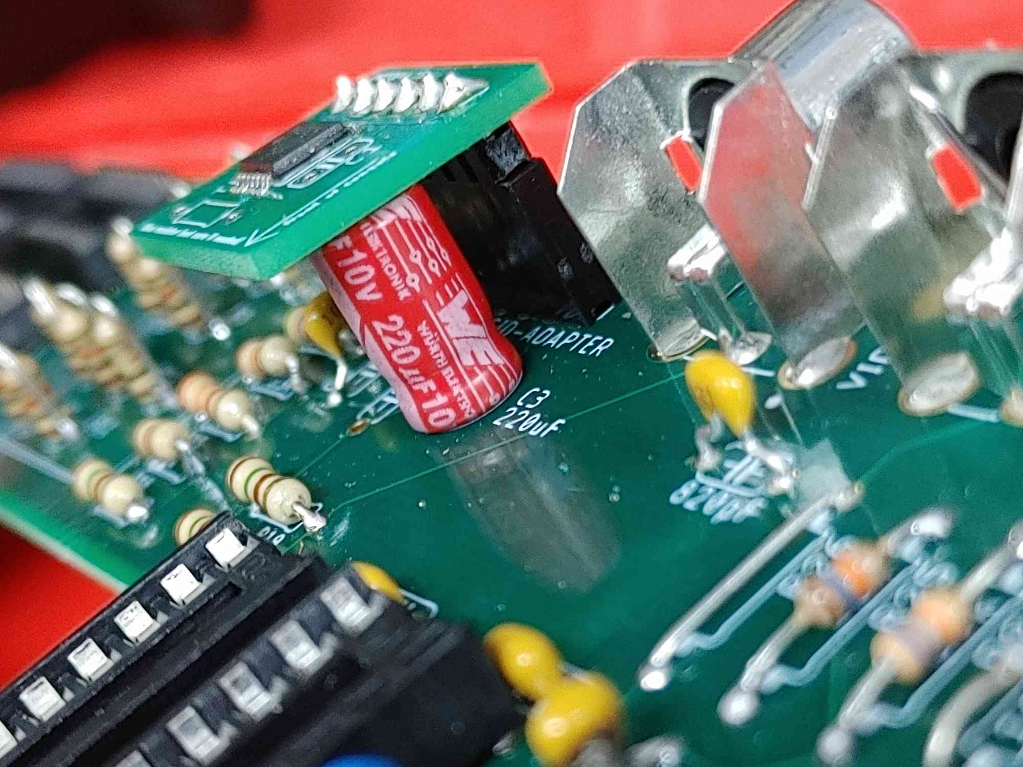
- Insert the video buffer amp module into the 6-pin female header, with the arrow pointing towards the front of the console.
- It will hang over the electrolytic capacitor next to it, but there should be enough clearance.
Step 20: Inserting Chips (Prelude)
- Next you'll be inserting chips into all these sockets you just soldered
- The chip names are printed on the the PCB, but they are now obscured by sockets.
- A layout diagram will come in handy for finding where chips live.
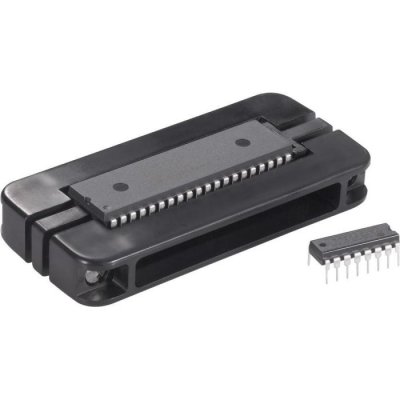
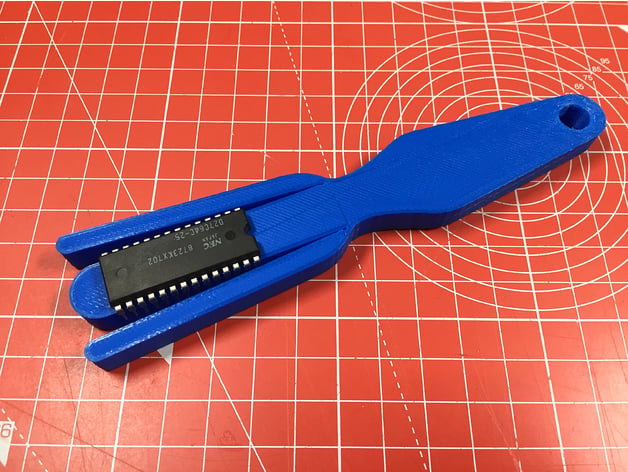
- It will also help greatly to have a Lead Forming Tool to straighten the chip pins, as they ship with their legs slightly bowed outward.
- Lead Forming Tools can be purchased commercially, or produced on a 3D printer.
- Simply place the chip on top of the middle bar and squeeze. The chip will now fit a socket perfectly.
Step 21: Gather your chips
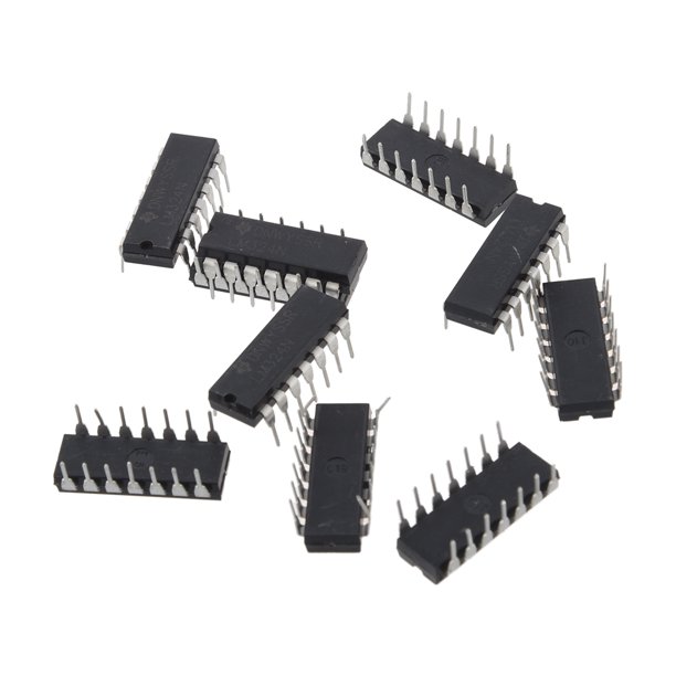
- 1x 74HC164N/E
- 1x HC151E (74LS151N)
- 2x HC08E (74LS08N)
- 2x HC257N
- 1x HC564N/E
- 2x HC573N
- 1x 7524CN/JN (AD7524JN)
- 3x HCT74N (74S74N/74LS74N/)
- 1x AC32N (74LS32N)
- 5x HC00E (7400N)
- 1x HC40103E (CD40103)
- 1x HC86E (7486N)
- 1x HCT30E (74AS30N)
- 4x HC4040E (4040N)
- 1x HC04E(7404N)
- 2x HC161N (74HC161)
- 1x LM358
Step 22: 1 x 74HC151
- Depending on the market, the HCT or AHC versions might be easier to get. These will work fine.
- The text on the chip might end in an N or an E. This denotes what factory they came from and doesn't matter here.
Step 23: 1 x 74HC30
- Depending on the market, the HCT or AHC versions might be easier to get. These will work fine.
- The text on the chip might end in an N or an E. This denotes what factory they came from and doesn't matter here.
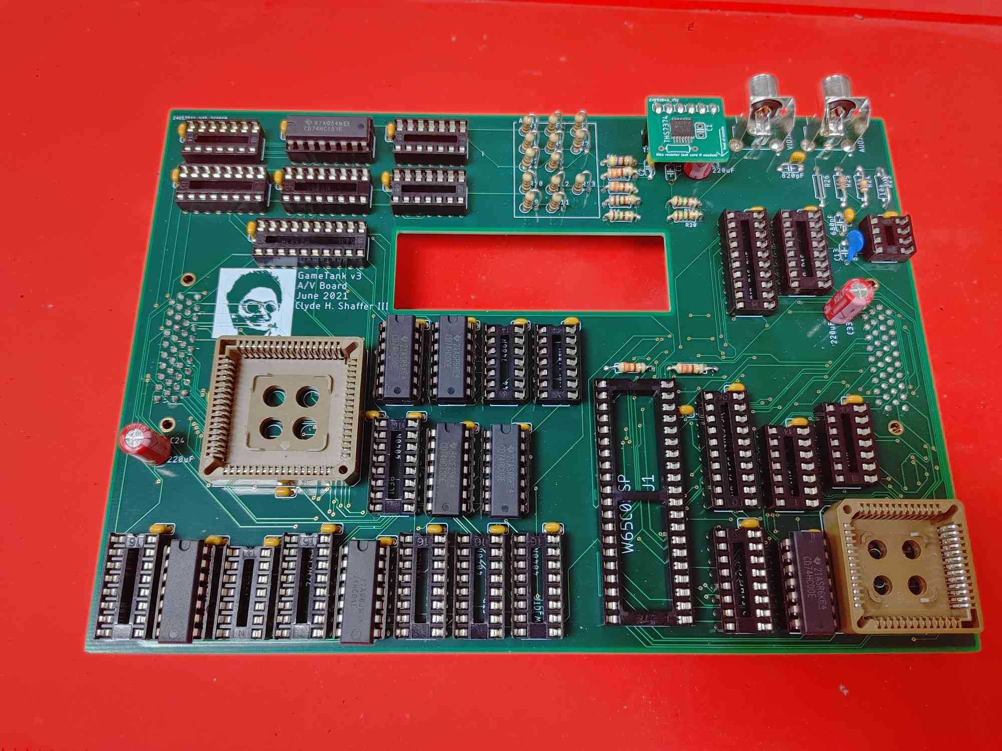
Step 24: 5 x 74HC00
- Depending on the market, the HCT or AHC versions might be easier to get. These will work fine.
- The text on the chip might end in an N or an E. This denotes what factory they came from and doesn't matter here.
Step 25: 1 x 74HC04
- Depending on the market, the HCT or AHC versions might be easier to get. These will work fine.
- The text on the chip might end in an N or an E. This denotes what factory they came from and doesn't matter here.
Step 26: 3 x 74HC74
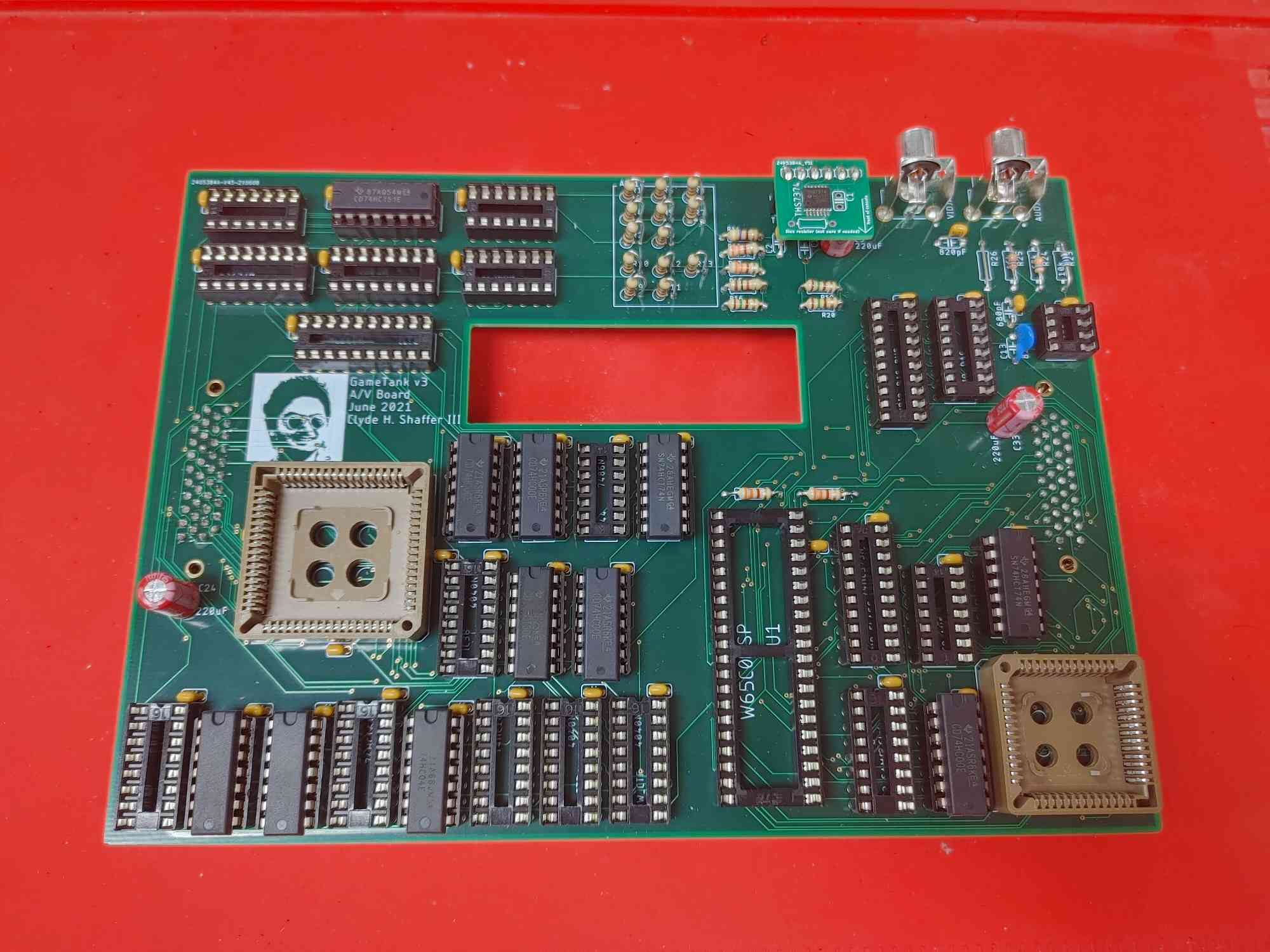
- Depending on the market, the HCT or AHC versions might be easier to get. These will work fine.
- The text on the chip might end in an N or an E. This denotes what factory they came from and doesn't matter here.
Step 27: 2 x 74HC161
- Depending on the market, the HCT or AHC versions might be easier to get. These will work fine.
- The text on the chip might end in an N or an E. This denotes what factory they came from and doesn't matter here.
- In your overall parts order is at least one 74AC161, but don't use it here! Save it for slot U$6 on the main board!
Step 28: 1 x 74HC32
- Depending on the market, the HCT or AHC versions might be easier to get. These will work fine.
- The text on the chip might end in an N or an E. This denotes what factory they came from and doesn't matter here.
Step 29: 2 x 74HC08
- Depending on the market, the HCT or AHC versions might be easier to get. These will work fine.
- The text on the chip might end in an N or an E. This denotes what factory they came from and doesn't matter here.
Step 30: 1 x 74HC86
- Depending on the market, the HCT or AHC versions might be easier to get. These will work fine.
- The text on the chip might end in an N or an E. This denotes what factory they came from and doesn't matter here.
Step 31: 1 x 74HC164
- Depending on the market, the HCT or AHC versions might be easier to get. These will work fine.
- The text on the chip might end in an N or an E. This denotes what factory they came from and doesn't matter here.
Step 32: 4 x 74HC4040
- Depending on the market, the HCT or AHC versions might be easier to get. These will work fine.
- The text on the chip might end in an N or an E. This denotes what factory they came from and doesn't matter here.
Step 33: 1 x 74HC40103
- Depending on the market, the HCT or AHC versions might be easier to get. These will work fine.
- The text on the chip might end in an N or an E. This denotes what factory they came from and doesn't matter here.
Step 34: 2 x 74HC573
- Depending on the market, the HCT or AHC versions might be easier to get. These will work fine.
- The text on the chip might end in an N or an E. This denotes what factory they came from and doesn't matter here.
Step 36: 1 x 74HC564
- Depending on the market, the HCT or AHC versions might be easier to get. These will work fine.
- The text on the chip might end in an N or an E. This denotes what factory they came from and doesn't matter here.
Step 37: 2 x 74HC257
- Depending on the market, the HCT or AHC versions might be easier to get. These will work fine.
- The text on the chip might end in an N or an E. This denotes what factory they came from and doesn't matter here.
Step 39: IDT7007 (Video RAM)
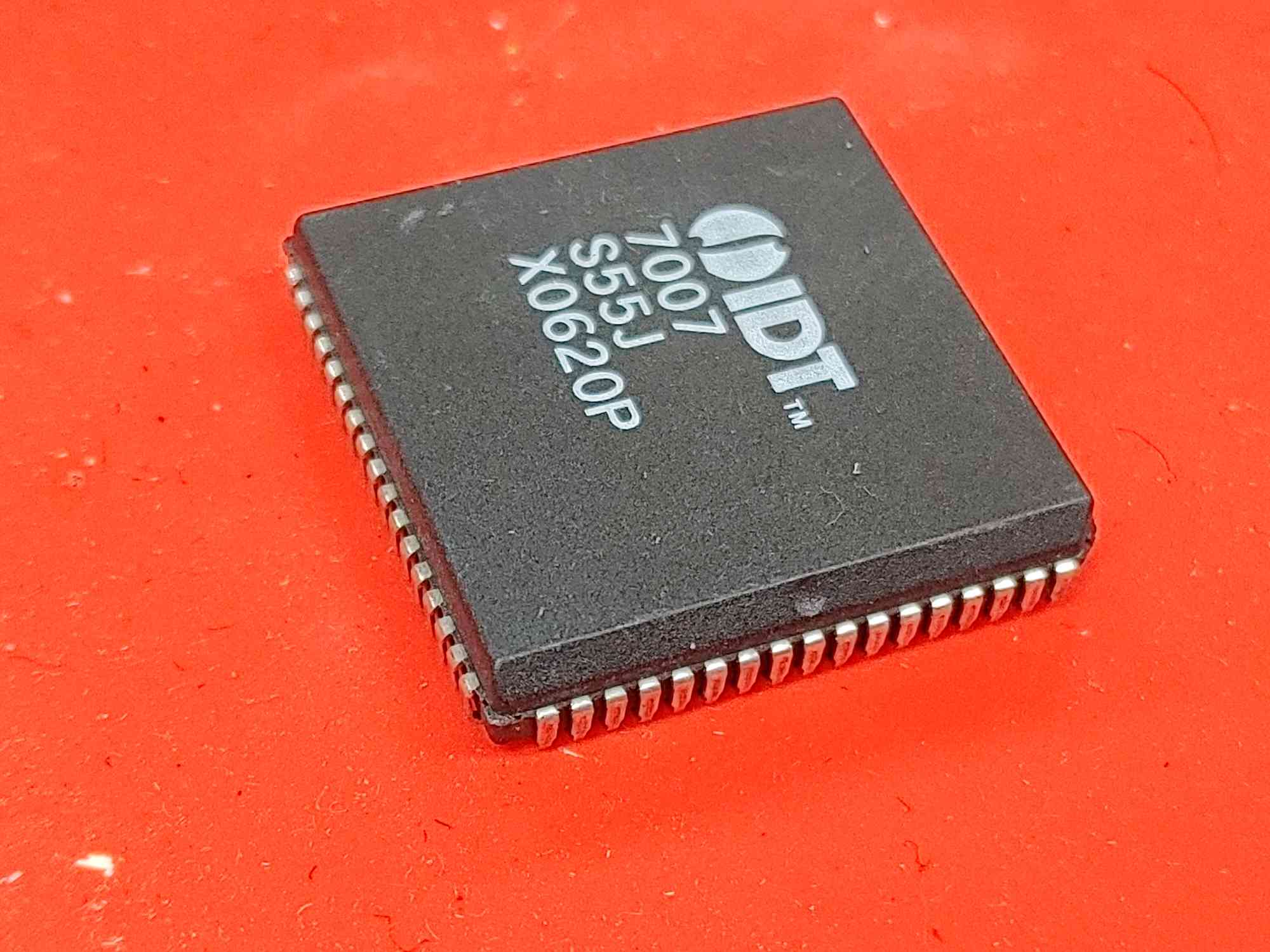
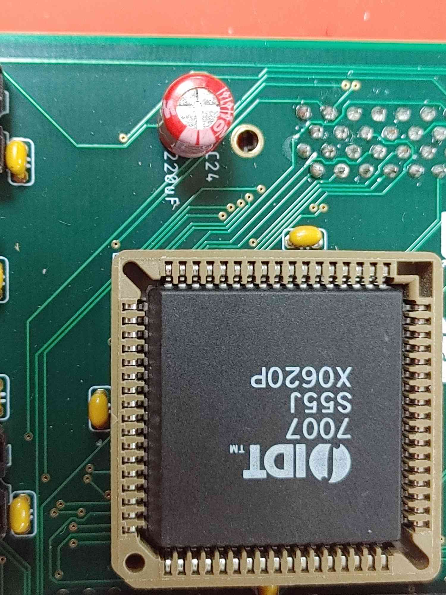
- Larger of the two square chips
- BE SURE TO align the dot on one edge of the chip to the direction of the arrow on the socket
- If inserted wrong you will need a special PLCC Removal Tool to extract it.
- To insert, just make sure the dot and the pins are lined up and press down firmly.
Step 40: IDT7137 (Audio RAM)
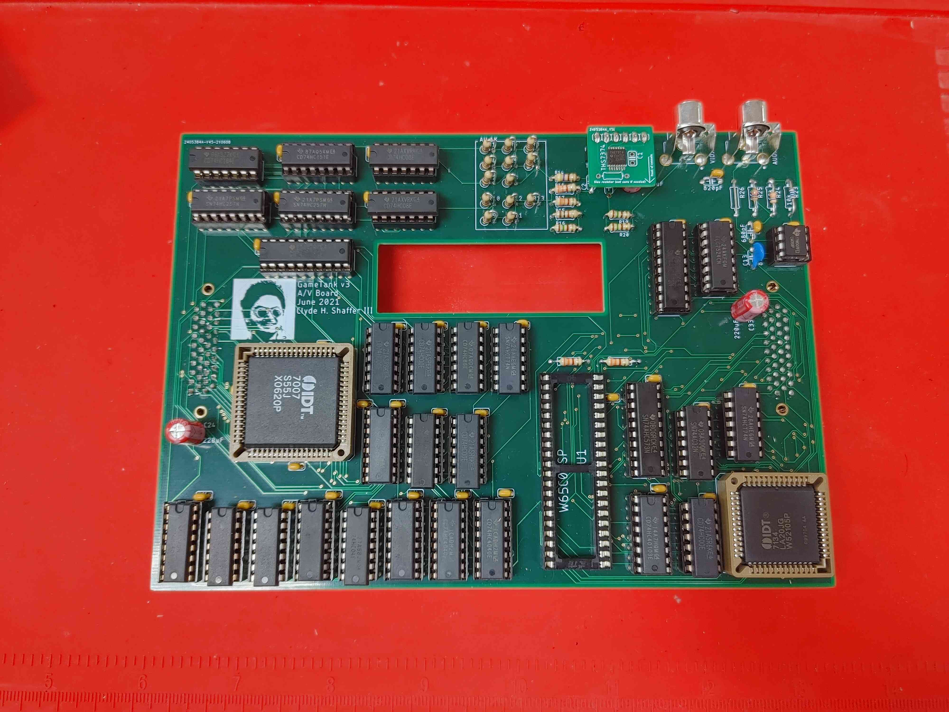
- Smaller of the two square chips
- Same warnings and advice for IDT7007 apply
- Double check the direction of the arrow, it isn't the same as the other socket!
Step 41: 6502 (Audio Coprocessor)
- One of the two 6502 chips in your parts order
- Not the 6522 VIA which is also a 40 pin DIP chip
- With this installed your A/V Board is complete! Well done!
X