GameTank Form-Factor Prototype
Now 70% more shaped like a game console!

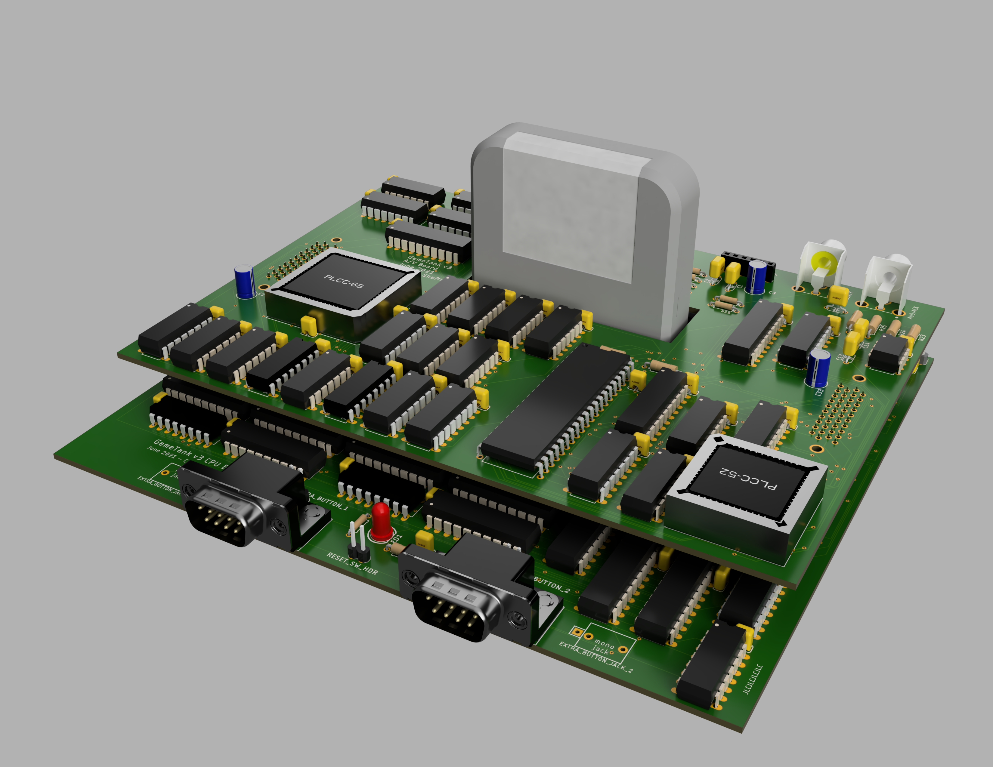
After fixing the last blitter bug, I sat down and combined the four board designs of the V2 prototype into a surprisingly compact two-board stack.
Combined PCB footprint is 7"x6" and hardly an inch and a half high.
I wondered at first if I'd have to go up to six layers but it ended up working out in just four. The autorouter seemed to have an easier time with the bottom board than the top board, strangely enough. Maybe it was because of the irregular shape.
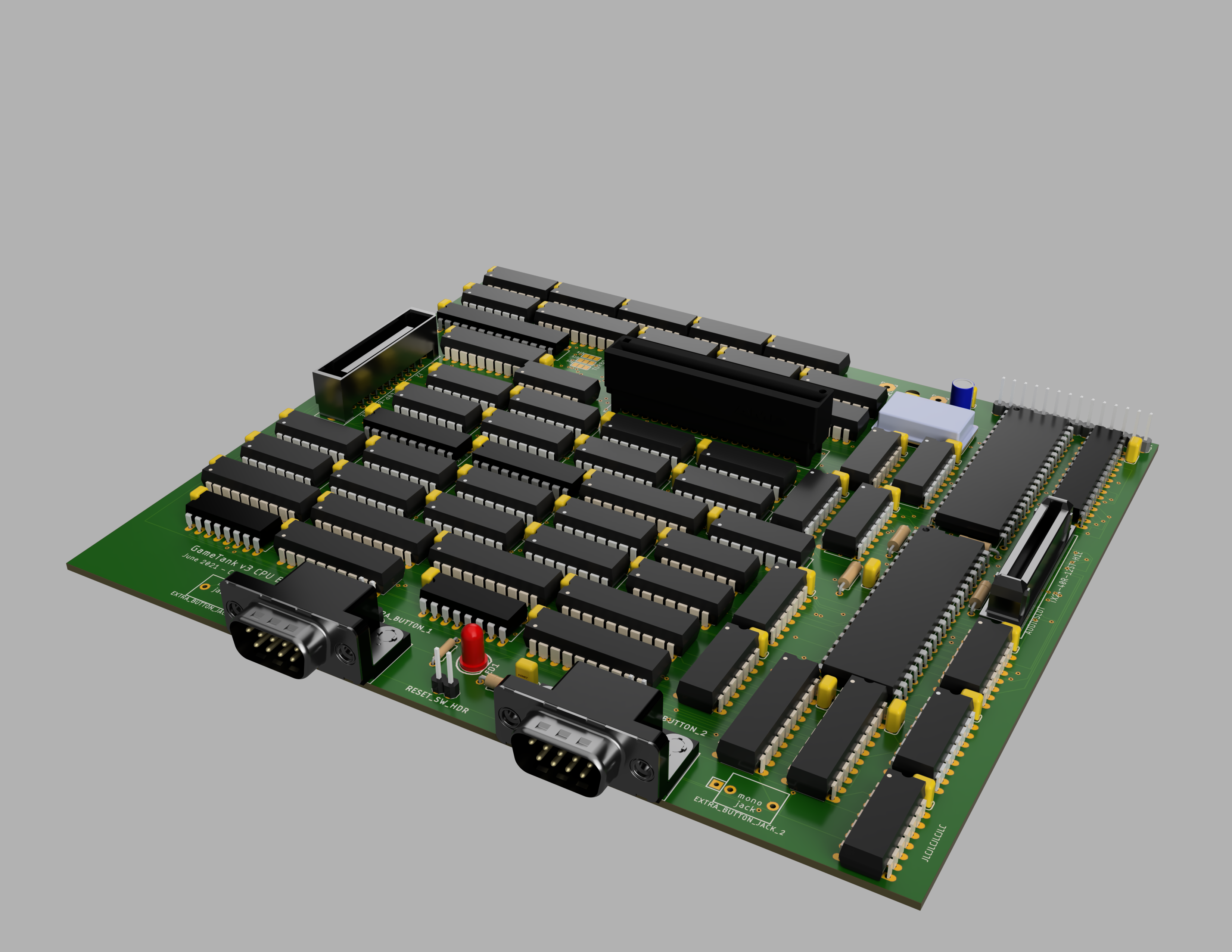
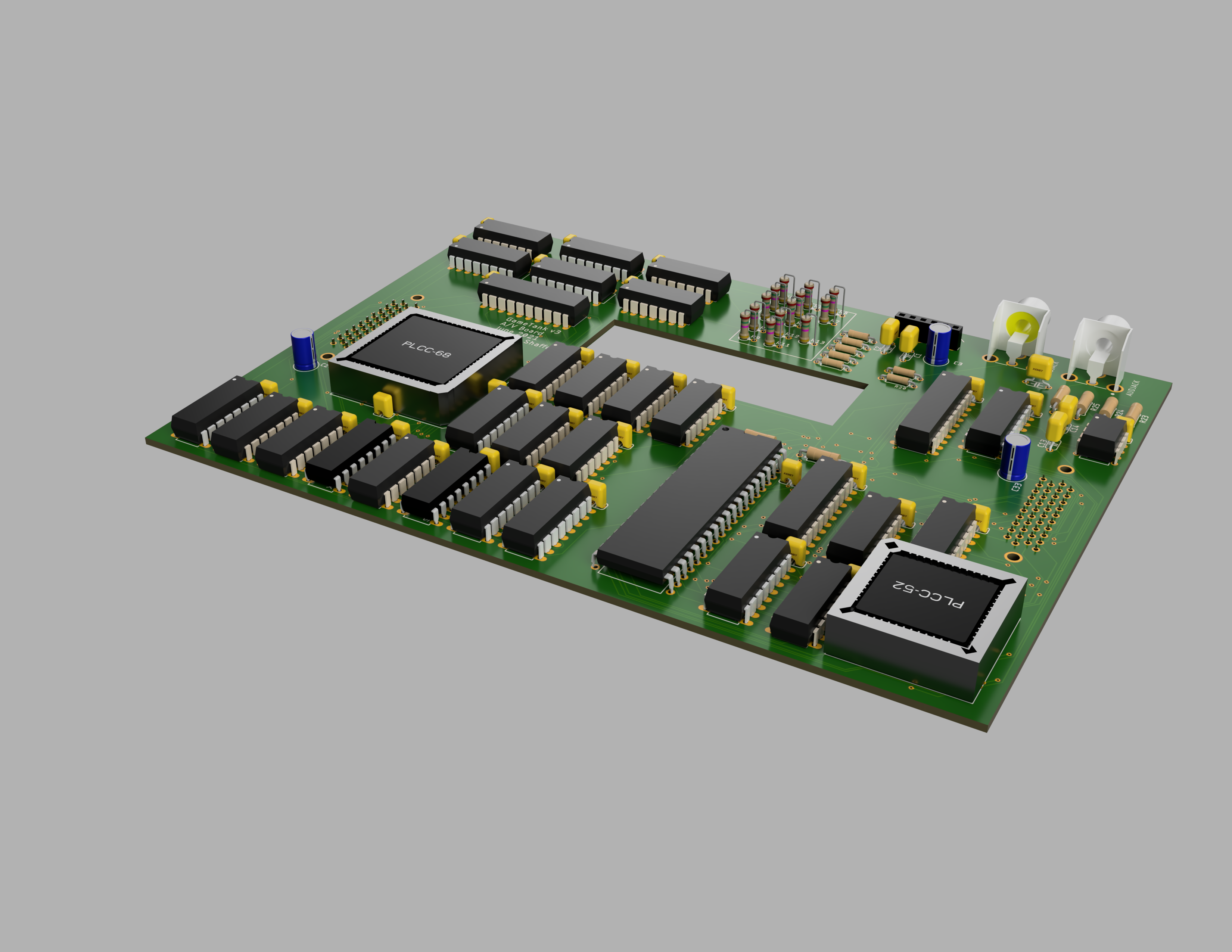
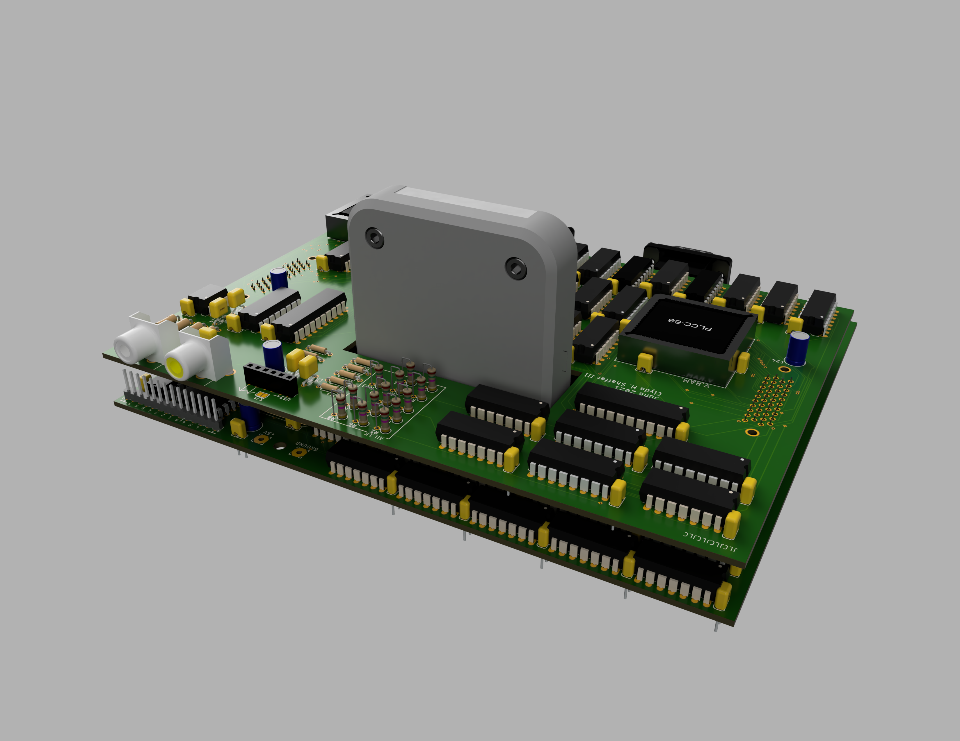
So that I could start designing the case, I exported the boards to Fusion360 and generated these high-res renderings.
(Well, I suppose the high-res wasn't necessary for case design but it does make for nice web content!)

The bottom board combines the blitter, address decoding, CPU, input ports, cartridge port, and VIA.
The keyboard switches used for Reset and two extra input buttons have been replaced with headers, to connect to case-mounted switches.
I've also left a footprint open in case I wanted to use a 3.5mm mono jack for the extra input buttons. This would, for instance, support connecting to certain exercise bikes. I think that would be kind of hilarious.

The top board holds the composite video circuit on one side and the audio coprocessor on the other. So I call it the "Signals Board".
It occurs to me at time of writing that I have no idea whether the big hole in the ground and power planes will be an issue. From what I've heard there is an unlimited number of ways to accidentally create an antenna. So hopefully this antenna isn't resonant at any frequencies I care about.

In the corner near the RCA connectors, I put a header that exposes twelve otherwise-unused VIA pins. Besides eventual expansion hardware, this is handy for debugging and profiling. I've also elected on this version to remove the existing linear regulator and instead leave a place to solder in a power module that I'll design later. This could either stick out the back a little, or go underneath the lower board. Initial testing could be easily done with a bench power supply, or I could just solder in a barrel connector and use a wall wart that already outputs 5V. The reason I switched from the regulator is mainly that it got very hot, even with a heat sink attached. I'd like to switch to a switched regulator instead, but still have some reading ahead of me to comfortably understand how to use one in a design.