GameTank Audio Subsystem
Beep Beep Boop Boop
Overview
The sound system for the GameTank is relatively simple. Seven registers control four channels, which are mixed down to a monophonic signal and output to the television. These channels are:
- Square Wave Channel 1
- Square Wave Channel 2
- LFSR Noise Channel
- Sample-Looping Wavetable Channel
Each channel has "control" register that sets both their volume and octave. Three volume bits control a digital potentiometer that sets each channel's contribution to the final mix. Three octave bits control a multiplexer that selects which output of a 74HC4040 counter is used to clock that channel's state. Each of the eight selectable divider outputs are twice the frequency of the last, which doubles the pitch. This lends itself well to generating musical sound, as the game software only needs to store pitch settings for a twelve note musical scale and trivially produce other octaves.
The two Square Wave channels each also have a pitch register for relatively fine-grained frequency control. These use the 74HC40103 counter IC, which count down from a specified binary number and emit a pulse when they reach zero. In the soundcard circuit, this pulse is used to trigger the 40103 to reload the value of the pitch register as well as advance the channel's aforementioned 4040 counter. It is important that the 40103 triggers the 4040 on the square wave and not the other way around, because the 4040 also converts the pulses into a square wave with 50% duty cycle.
The Noise Channel uses a Linear Feedback Shift Register to produce a series of pulses with pseudorandom duration and spacing. The resulting sound is similar to radio static, or perhaps a rushing jet of water if the former is no longer ubiquitous enough for comparison. This channel does not have a pitch control, but can have its volume and input clock varied by its control register. The volume control is useful for modulating the noise to sound like a percussive instrument such as a snare drum, or even a more drawn out sound such as sliding a box. While noise doesn't typically have a defined pitch, it does have range of frequencies and harmonics produced by being quantized on both time and amplitude. In other words, the signal spends most of its time at either 0 volts or 5 volts, and only changes in step with the input clock which does have a defined frequency. This means that changing the octave control on the LFSR channel will produce a distinct change in the tone of the noise. For example, this allows the noise channel to be used for deeper kick drums as well as higher snare drums.
The last channel, the Wavetable Channel, is a bit more versatile but also requires a bit more setup. The soundcard has a RAM chip on board which holds 4096 bytes, and can be accessed simultaneously by the CPU and the soundcard. Like the Square Wave channels, the Wavetable Channel has a second register in addition to the volume/octave register. This Sample Address register specifies the location of the beginning of an audio clip. Naturally, due to the small size of the Wavetable RAM, these audio clips are necessarily quite short. Even a sound that fills the whole space would be less than a second long, so this channel is best suited towards storing single cycles of complex sounds the other channels could not produce. This channel has a counter that begins at the location specified by the Sample Address register, and marches forward at the pace of the octave clock. The data output pins of the RAM are connected to a DAC chip which converts the represented binary number into a voltage. The end of a sample is determined by reaching a byte with a value of 0xFF, which causes an 8-input NAND gate to drive its output low and strobe the reload pin of the address counters, thus restarting the sample.
Challenges
Before getting into this project I hadn't studied electrical engineering very deeply at all. Much of my initial momentum on this endeavor was thanks to being able to carry over boolean logic assumptions from computer programming into working with the digital logic of 74HC integrated circuits. When dealing with mixing analog signals however, many of these assumptions go right out the window and a new method of thinking is required.
One consequence of my analog ignorance wasn't apparent until I mixed the channels together. After first assembling and testing the soundcard, it exhibited a strange behavior where any one channel's volume setting would affect the loudness of the others. Eventually I realized that although the digital potentiometers were successful at varying the output voltage of each channel, they also created a ground path at the minimum volume setting that would mute the final mix by pulling it strongly to 0V. To work this out I had to desolder the resistors in my initial attempt at a passive mixer and connect wires that would let me experiment on a breadboard. The solution I arrived at was to AC-couple the channels to the mixer, letting audible frequencies through but blocking the effect of the hard pull to ground. Once I had an arrangement I felt comfortable with, I ordered a small addon PCB that would connect where the original resistors did, and patch in the new mixer.
Another audio circuit challenge that I'm actually still wrestling with is that during the time I've been working on this project, the DS1866 digital potentiometer apparently went out of production with no direct replacement. There are a handful of parallel interface digital pots that exist, but they all only have two bits of input compared to the DS1866's three. Thus they have only four positions instead of eight. Perhaps I will have to completely rethink my setup for converting these audio chanels from digital to analog, and how I mix them...
Media
Initial square channel breadboard prototype, controlled by an Arduino
For some reason Famitracker outputs steadier MIDI than FL Studio... Got my multiplexers in the mail and now can freely roam the octaves pic.twitter.com/K8gzUxnZk9
— Clyde Shaffer (@clydeshaffer) August 16, 2019
Demonstrating the noise channel on live hardware with a simple sound test app
And the result? Tasty noise! pic.twitter.com/8MD02vV2An
— Clyde Shaffer (@clydeshaffer) July 4, 2020
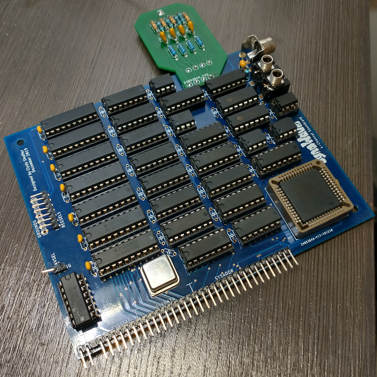
Attaching the mixer patch PCB