Graphics, Part 1
Generating a black-and-white video signal for analog TVs

A game console needs some way to output an image, and for the GameTank I chose to generate composite video. This choice was largely driven by nostalgia for plugging in consoles with the yellow, white, and red plugs. As a kid, it made sense to me how sound waves could be translated to a changing voltage, but I was puzzled at how information as rich as a moving image could also be funneled through a single wire.
The answer is that the whole image is not sent at once. Rather, it is broken down into rows which are sent from left-to-right and top-to-bottom. For a grayscale television image, the voltage on the wire at a given time transmits the brightness of a single pixel. (Though strictly speaking it isn't quite a "pixel" as the left-to-right position isn't quantized to a grid.) To transmit a color image, a technique is used that can simultaneously encode extra information onto a single signal. For this entry I'll focusing on monochrome television and the development of my initial black-and-white video prototypes.
An article that I highly recommend reading is "ATARI PONG E CIRCUIT ANALYSIS & LAWN TENNIS" by Dr Hugo Holden. Although my video board design would diverge from the Pong circuit early on; it was reading and rereading Dr Holden's walkthrough of the circuit's architechture and the requirements of the video signal that taught me what I needed to know to start experimenting.

The television expects to receive 262.5 scanlines 60 times per second. To generate this, a "clock" is used that produces a high frequency square wave at a fixed frequency. Many systems that interface with a television use a multiple of what's called the "colorburst" frequency of 3.579545MHz (or 315/88 MHz). This prototype will be black-and-white only, but I would eventually move on to color so I'd purchased clock generators at 4x the colorburst frequency or 14.318MHz. To denote the divisions between consecutive lines as well as the end of each frame, the signal is brought down to 0 volts for a specific amount of time. These "blanking periods" are called Horizontal Synchronization (H.Sync) for separating lines, and Vertical Synchronization (V.Sync) for separating frames.
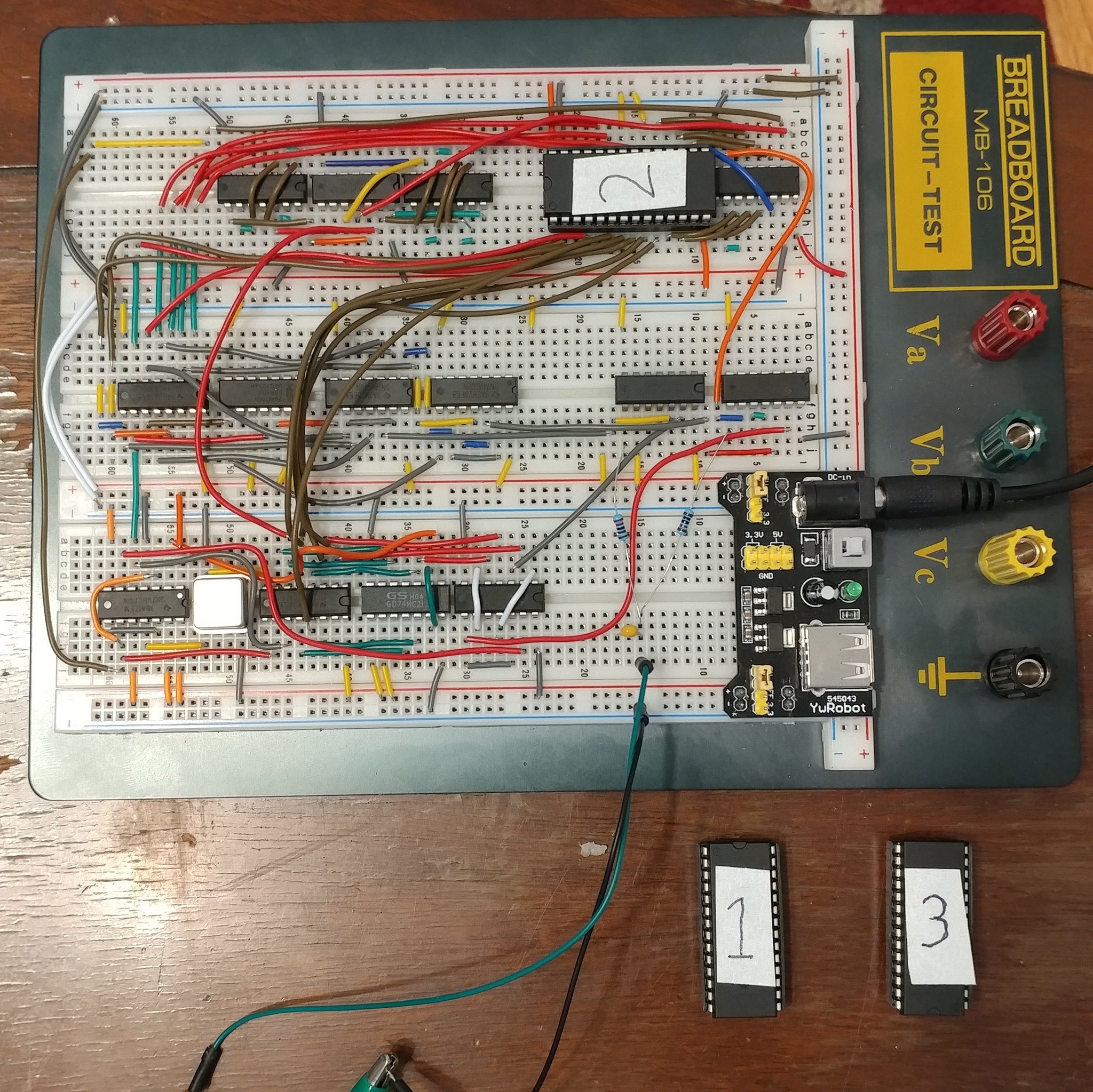
The 74HC family of logic circuit ICs includes many useful functions; such as logic gates, counters, and flip-flops. When the clock signal is applied to a counter it increments a binary number represented by high or low voltages on its output pins. With a few logic gates it is straightforward to determine when a certain number has been reached, and the counter can be reset. This essentially creates a new clock signal divided by an arbitrary whole number denominator of the original. By counting up to the correct divisor, the original 14.3MHz clock can turn into our H.Sync pulse at 15,720Hz (262 lines * 60Hz) as well as our V.Sync pulse at 60Hz. This will allow the receiving television to "lock" onto the signal.
Of course with only the sync pulses set up, the TV has locked onto a whole lot of nothing. So to produce a picture I want to differ the voltage supplied between sync pulses. This is where I start to diverge strongly from the Pong cirtcuit. The Pong circuit has dedicated circuitry for each "object" that appears on the screen. See, besides producing the sync signals the aforementioned counters also give a precise indication of the location of the pixel being sent to the screen. By applying a few more logic gates to these counters a circuit designer can choose to send bright pixels when inside a desired rectangular area on screen, for instance. Instead, I would make use of a ROM chip programmed with image data.
A ROM chip is not all that unlike a logic gates. It has a set of input pins, and a set of output pins. The important distinction is that the behavior of an AND gate or an OR gate is fixed, to output the logical AND and logical OR results respectively. The ROM chip is instead programmed ahead of time with a sort of "table" of data. Its inputs constitute a binary number of 13 or so bits, and its output an 8-bit number retrieved from the table at the line number given to its input. By connecting its input pins to the outputs from the counters, the ROM chip can be made to output all of its entries over and over, in rapid succession.


While my eventual video card design for the GameTank would use a whole byte to represent each pixel, this prototype would efficiently pack eight pixels into each byte at the cost of only being able to have pixels be completely bright or completely dark. This was accomplished by connecting the ROM chip's eight outputs (which are updated simultaneously) to the inputs of a shift register. The shift register would temporarily store a copy of the byte, and send out one bit at a time when triggered by the clock signal.
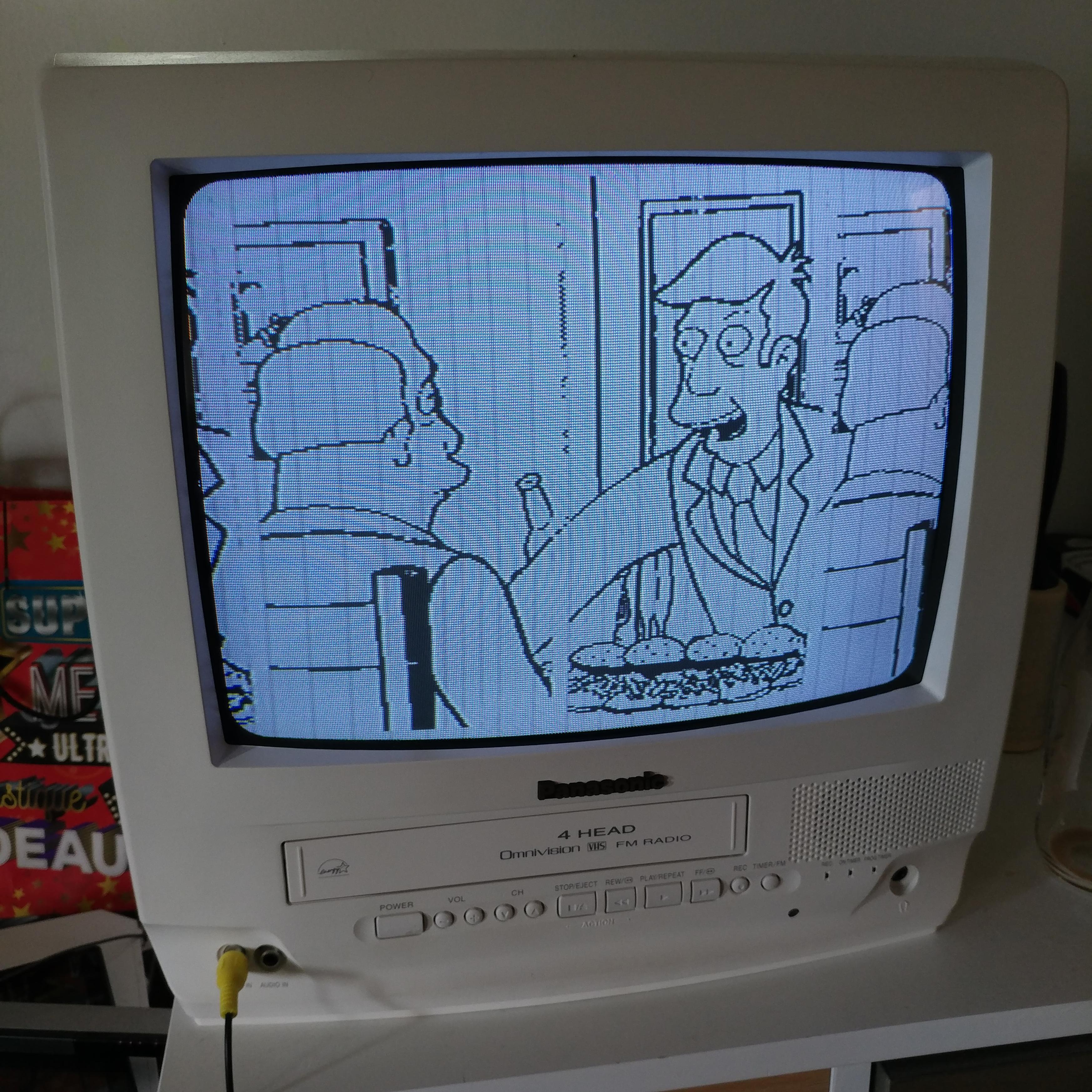
Besides the breadboard, I would make two prototypes that produced a static black and white image at 256x256 size. The first would come to be known as "Steamed RAMs", a reference to a 1996 segment from The Simpsons that became a meme in 2016 which I was a little obsessed with. I'm still a little obsessed with it, but I was then too. The meme format would usually be some title such as "Steamed Hams but it's _____" followed by some modified image or video of the scene. I worked out a conversion method using Photoshop and a hex editor (utility program for directly editing the bytes of a file as hexadecimal numbers) to quickly scale down, clean up, and burn image files to the ROM chip.


I'd found that my process for converting images to black and white was also useful for adding images to the screenprinting on printed circuit boards. So I thought I'd have a bit of fun with it and make the board self-referential. That is, I'd put the same image on the screenprint that I would burn onto the ROM chip. Then I'd order the board, solder the circuit, and take a few pictures to score some validation on social media with my "Steamed RAMs" or "Steamed Hams but it's a Circuit Board" meme. Did I mention I did this in 2019, well after that meme's time?
You'll find that overwrought jokes that are hilarious to me, amusing at best to others, and far outside commonly accepted comedic timing are the running theme in most of my works.
